
This is a line-following robot I built using Arduino and C programming, 18650 cells, and IR light detecting sensors. Below are some photos of the robot, my code for autonomous control, and a video of the robot in action. This was part of my Integrated Engineering 230 project coursework at UBC:
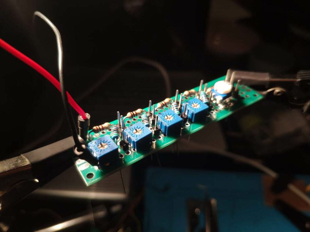
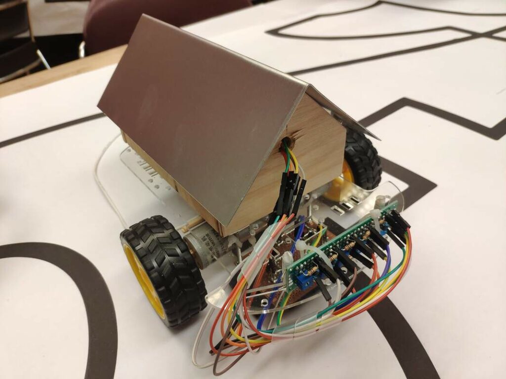
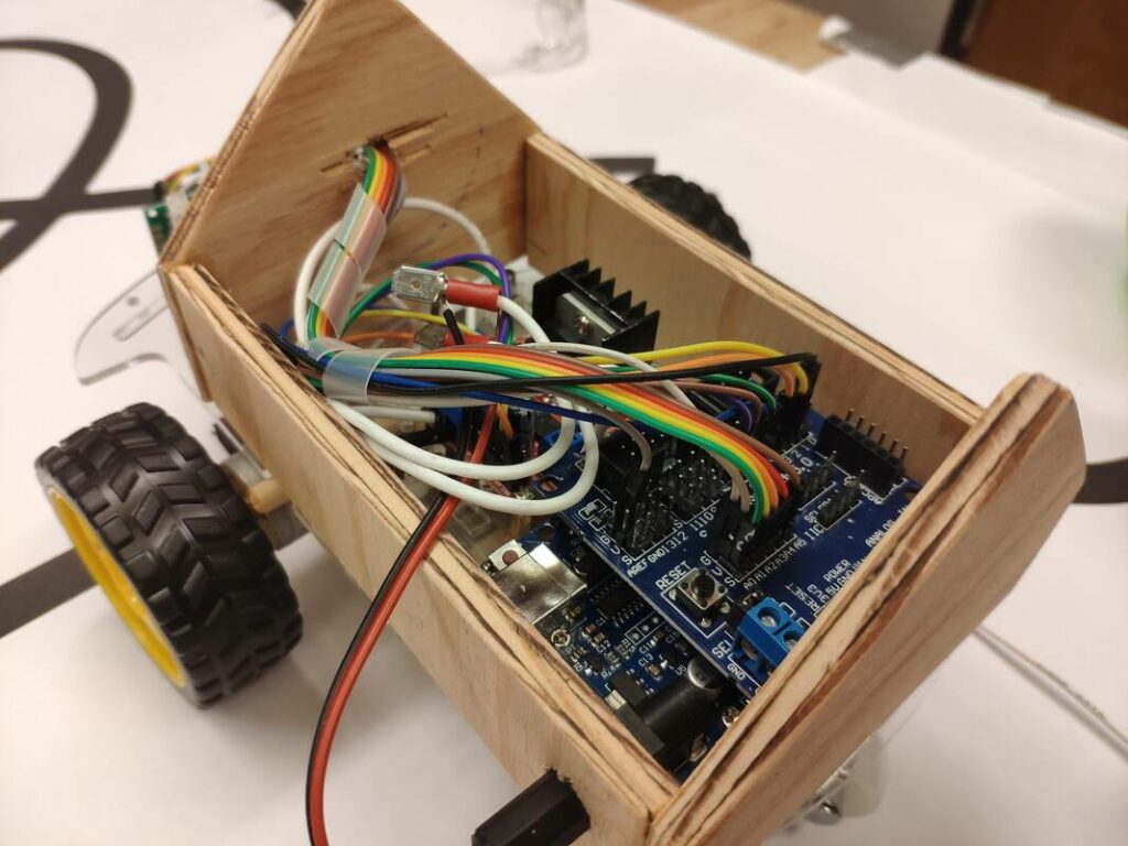
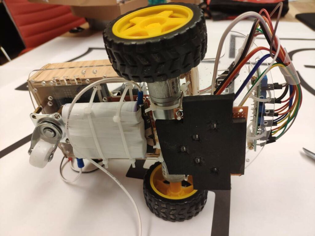
The 18650 cells provide sufficient current to my upgraded motors to keep the bot’s torque delivery consistent across multiple runs, and the foam shielding helps protect the 5 IR sensors from reading false positives. You may notice a callback to the classic IGEN birdhouse shop training project as well! In the code below, the primary part of interest occurs in my calculation of each sensor’s value as a mass, affecting a moment about a set point. This allows me to determine the center of mass of all sensors to determine where to go, instead of setting up cases for each possible sensor value combination and having to use threshold values for “black” and “white.” I chose to do this because in my testing, these sensors are so unreliable and inconsistent that this method’s error tolerance is needed.
/* Arif Janmohamed's IGEN 230 line following robot code.
 * December 7th, 2021
 * arif.antoine@gmail.com
 */

#include

// Motor control pins : L298N H bridge
const int enAPin = 6; // Left motor PWM speed control
const int in1Pin = 7; // Left motor Direction 1
const int in2Pin = 5; // Left motor Direction 2
const int in3Pin = 4; // Right motor Direction 1
const int in4Pin = 2; // Right motor Direction 2
const int enBPin = 3; // Right motor PWM speed control

/// sense declarations
const int sensor0 = A0;  // Analog input pin that the sensor is attached to
const int sensor1 = A1;
const int sensor2 = A2;
const int sensor3 = A3;
const int sensor4 = A4;

const double maxSpeed = 220; //value from 0 to 255. this is full forward ahead speed. Set maxspeed more intelligently in future?

int sensor0Value = 0;        // value read from the sensor, set to zero initially
int sensor1Value = 0;
int sensor2Value = 0;
int sensor3Value = 0;
int sensor4Value = 0;

int output1Value = 0;        // value output to arduino scaled (analog out)
int output2Value = 0;
int output3Value = 0;
int output4Value = 0;
int output5Value = 0;

int outputArray[5]; //sensor outputs scaled array

double mass = 0;// total mass of all sensor outputs combined
double moment = 0; //sum of moments caused by each sensor mass
double centroid = 0;// between 0 (full left) and 4 (full right), equal to moment/mass.
int whiteIndex = 0; //for counting number of motion cycles without vision of line

/* sense function finds sensor values, processes and offsets these,
 * calculates direction to move in, and tells yeet function to move
 * in said direction.
 */
void sense() {

  //reset values each cylce
  moment = 0;
  mass = 0;
  centroid = 0;

  // read the analog in value of each sensor:
  sensor0Value = analogRead(sensor0);
  sensor1Value = analogRead(sensor1);
  sensor2Value = analogRead(sensor2);
  sensor3Value = analogRead(sensor3);
  sensor4Value = analogRead(sensor4);

  // map it to the range of the analog out array
  outputArray[0] = map(sensor0Value, 0, 1023, 0, 255);
  outputArray[1] = map(sensor1Value, 0, 1023, 0, 255);
  outputArray[2] = map(sensor2Value, 0, 1023, 0, 255);
  outputArray[3] = map(sensor3Value, 0, 1023, 0, 255);
  outputArray[4] = map(sensor4Value, 0, 1023, 0, 255);

  //hacky way to account for sensor 1's lower range (40ish when white and 130 when black instead of 14/150.)
  if(outputArray[1] < 50) {
    outputArray[1] = outputArray[1] - 30;
    if(outputArray[1] < 15){
      outputArray[1]=15;
    }
  }
  else if(outputArray[1] > 100) {
    outputArray[1] = outputArray[1] + 20;
  }

  // print the results to the Serial Monitor:
  Serial.print("sensors = ");
  for(int i = 0; i < 5; i++){
    Serial.print(outputArray[i]);
    Serial.print(", ");
  }
  Serial.print("\n");

  //calculate sum of moments and masses
  for(int i=0; i<5; i++) { //output array - 10 is to reduce background noise from sensors
  moment += (outputArray[i] - 10) * i;
  mass += (outputArray[i] - 10);
  }

  // find centroid, where centroid should equal to the direction of most black line density between 0 and 4 (2 is continue straight)
  centroid = moment / mass;

  Serial.print("centroid = ");
  Serial.print(centroid);
  Serial.print("\n");
  Serial.print("total mass = ");
  Serial.print(mass);
  Serial.print("\n");

  // if mass is under 95ish, we are probably over white.
  if(mass > 95) {
    yeet(centroid, maxSpeed);
    whiteIndex = 0;
  }
  else if(mass < 95 && whiteIndex < 6) { // here we are over white but keep going straight for 6 cycles to get over gaps in track.
    yeet(2, maxSpeed);
    whiteIndex++;
  }
  else { //only backup if you tried to go forward six cycles and still saw no black. backup at a turn seeing as almost every sharp corner is a left hand corner.
    yeet(2.35, -maxSpeed);
  }

  // defines milliseconds of movement
  delay(50);

  yeet(2, 0); //do nothing

  // defines milliseconds of stop between motion cycles
  delay(15);
}

/* yeet function controls movement of robot wheels.
 * it has no sensor value reading and only works with
 * all the data gathered by the sense() function.
 */
void yeet(double centroid, double maxSpeed) { //max speed 255

  //sensorsums reset
  int leftSensorsSum = 0;
  int rightSensorsSum = 0;
  int middleSensorsSum = 0;

  //rebase motor factors to -1 to 1:
  double leftMotorFactor = centroid - 1.0;
  double rightMotorFactor = 3.0 - centroid;

  // prevent over-speedy motors
  if(leftMotorFactor > 1.0) {
    leftMotorFactor = 1.0;
  }
  if(rightMotorFactor > 1.0) {
    rightMotorFactor = 1.0;
  }

  //method for encouraging spin turns more:
    for(int i = 0; i<3; i++) {
      leftSensorsSum += (outputArray[i] - 10); //leftSensorsSum represents the sum of the three leftmost sensor values (high if black low if not).
    }
    for(int i = 4; i>2; i--) {
      rightSensorsSum += (outputArray[i] - 10);
    }
    if(leftSensorsSum > 250 && rightSensorsSum < 160) { // turn hard left and make the left motor spin more negatively.
      leftMotorFactor = leftMotorFactor - 0.5;
    }
    else if(rightSensorsSum > 250 && leftSensorsSum < 160) {
      rightMotorFactor = rightMotorFactor - 0.5;
    }

  double leftSpeed = maxSpeed * leftMotorFactor;
  double rightSpeed = maxSpeed * rightMotorFactor;

  //right motor offset down to compensate for SHITTY H BRIDGE found by testing motor rpm against each other at each pwm range.
  //works if rightSpeed is pos or neg.
  rightSpeed = rightSpeed - (0.238 * rightSpeed - 0.296); //found by measuring offsets at each pwm range and then finding best fit equation.

  Serial.print("lmf = ");
  Serial.print(leftMotorFactor);
  Serial.print(" rmf = ");
  Serial.print(rightMotorFactor);
  Serial.print("\n");

  //prevent too high speeds and too low speeds
  if(leftSpeed > 255) {
    leftSpeed = 255;
  }
  else if(leftSpeed < -255) {
    leftSpeed = -255;
  }
  if(rightSpeed > 255) {
    rightSpeed = 255;
  }
  else if(rightSpeed < -255) {
    rightSpeed = -255;
  }

  //set right motor to go forward if speed positive, backwards if negative
  digitalWrite (in4Pin, rightSpeed <= 0 ? HIGH : LOW);
  digitalWrite (in3Pin, rightSpeed > 0 ? HIGH : LOW);

  //set left motor to go forward if speed positive, backwards if negative
  digitalWrite (in1Pin, leftSpeed <= 0 ? HIGH : LOW);
  digitalWrite (in2Pin, leftSpeed > 0 ? HIGH : LOW);

  //set motor speed (direction set before)
  analogWrite(enAPin, leftSpeed < 0 ? -leftSpeed : leftSpeed );
  analogWrite(enBPin, rightSpeed < 0 ? -rightSpeed : rightSpeed );

  Serial.print("left motor speed = ");
  Serial.print(leftSpeed);
  Serial.print(" right motor speed = ");
  Serial.print(rightSpeed);
  Serial.print("\n");
}

void setup() {

pinMode(enAPin, OUTPUT);
pinMode(in1Pin, OUTPUT);
pinMode(in2Pin, OUTPUT);
pinMode(in3Pin, OUTPUT);
pinMode(in4Pin, OUTPUT);
pinMode(enBPin, OUTPUT);

// initialize serial communications at 9600 bps:
Serial.begin(9600);
}

void loop () {
sense(); //sense calls yeet so this is all I need
}
Project Outcomes
Expands
our students’ access to and confidence with MIG and TIG processes
Builds
our shop supervisors’ talents as educators and improves our student body’s collective knowledge and ability as manufacturers
Unlocks
Potential for more ambitious student projects within the IGEN capstone design community
Skills and Learning
•••••
Leading hands-on technical training of 5-10 person groups
•••••
Creating well-documented, clear written curriculum and tests
Leave a Reply