

This year, we decided to try designing and manufacturing our own in-house carbon fiber suspension links as opposed to welded 4130 steel links. Carbon links have the potential to be stiffer and lighter, and also help reduce unsprung mass in our vehicle. They can also have a larger second moment of area relative to low-diameter and thicker steel tubing, improving buckling strength.
This of course is a high-risk project, so we were included from the start to ensure that the necessary testing was done to validate our design and manufacturing methods.
We began early in the year by working very closely with suspension members (especially Austin Chuong, who was leading the project on the sus side). We had several design for manufacturing and assembly focused meetings where we advised the team on machined insert design considerations and moldmaking considerations to try and maximize the likelihood we would have the time to manufacture these links at an acceptable quality (quite a challenge in a short span of time).
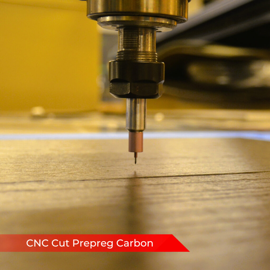
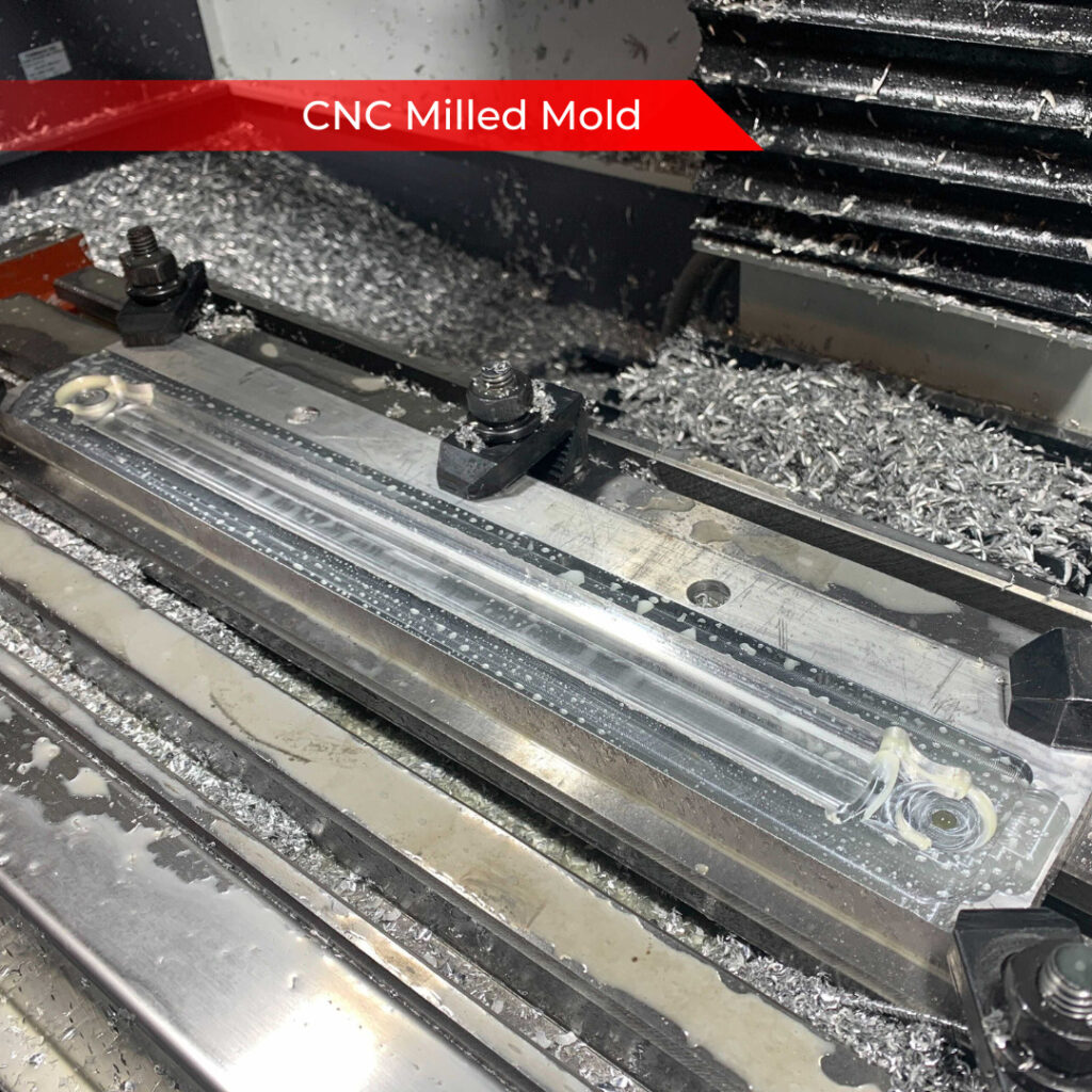
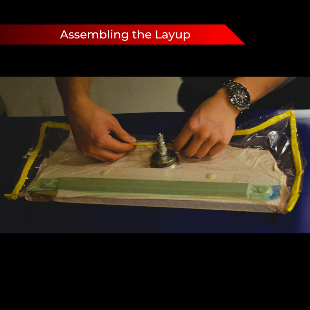
At the same time, we began machining test inserts and doing test layups to quantify strength. Below is a step-by-step process summary. We used a 9-layers of alternating spread-tow woven and unidirectional 0 degree prepreg, wrapped around a rohacell core and cured in an aluminum half-mold:
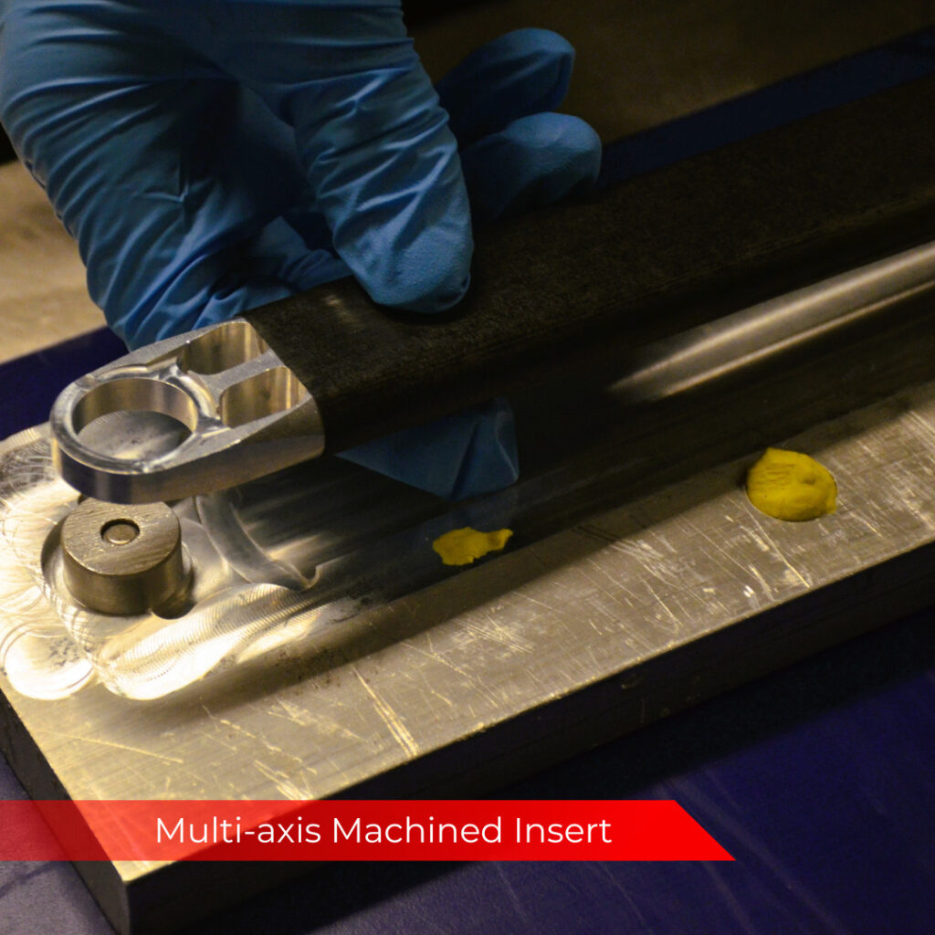
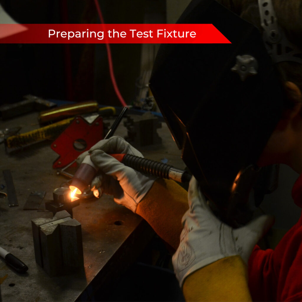
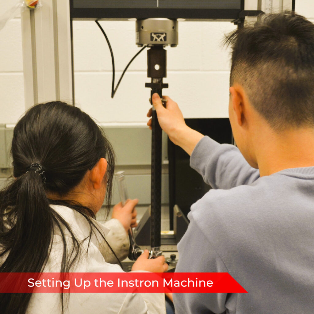
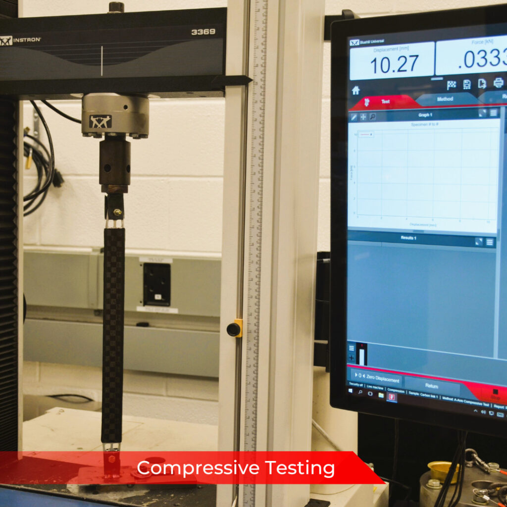
What we found was that the machined inserts weren’t properly bonded to the carbon tube shell via co-curing. We needed to remove, prepare surfaces, and then epoxy the inserts back into the carbon link, and then we performed testing. Our objectives were to match 13kN in compressive load (failure load of previous steel links), while maintaining a similar or greater stiffness. Both objectives were reached, as seen in the bottom right test. The top left is with the co-cured inserts before epoxy.
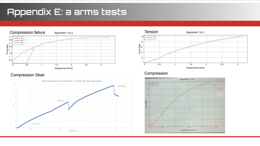
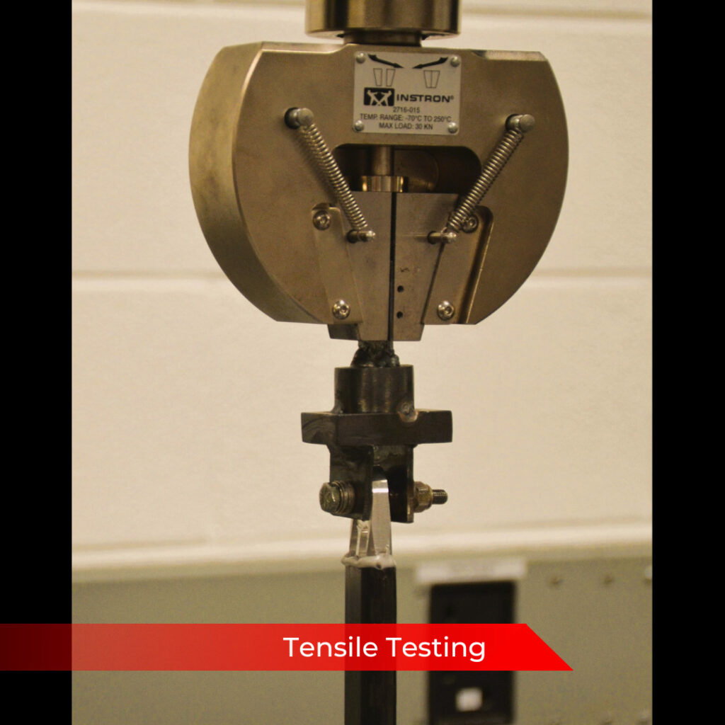
We found that the CF link displaced 0.5mm under compression at 4kN whereas our previous steel links displaced 0.875mm at 4kN. The failure mode in both tension and compression was bond failure, with buckling never experienced.
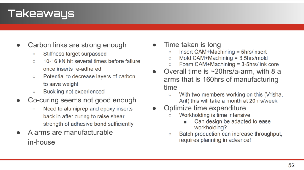
These were our main takeaways from testing, which informed our next steps for final manufacturing:
For the final A-Arms, my co-lead Vrisha and I ended up working with Austin to ensure that all inserts could be made with minimal CNC operations, and that we could reuse our molds for as many pieces as possible, taking advantage of a symmetric design and producing each individual link separately epoxying the A-arm together at the insert, as had been validated in our testing above.
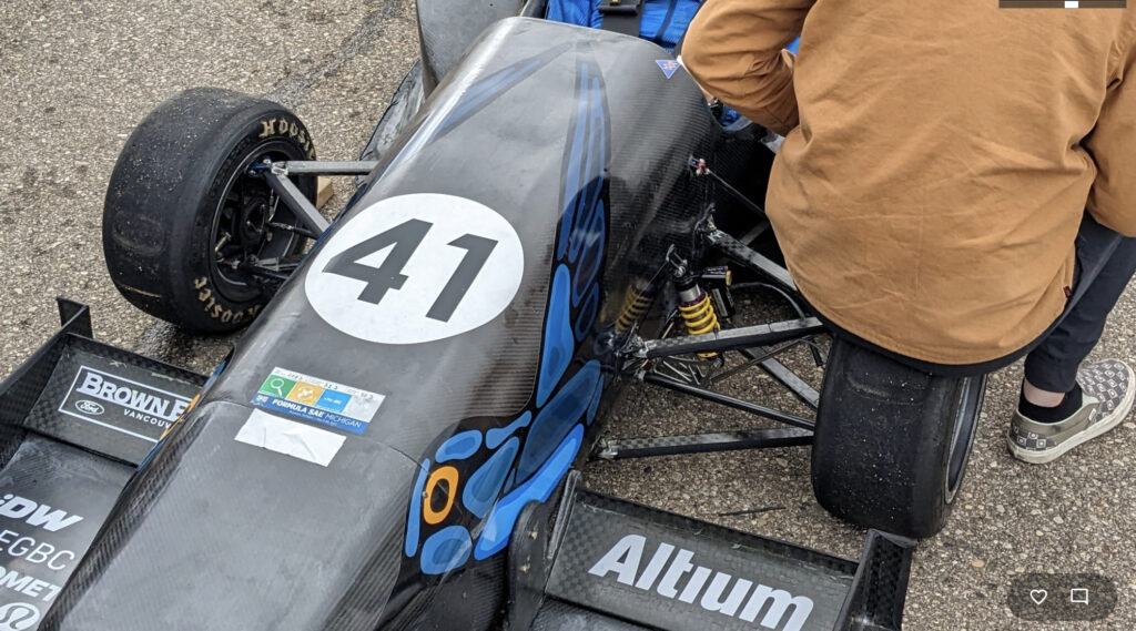
The A-Arms held up at comp, and have held up on rigorous shakedown testing since!
Design Outcomes
13kN
Maximum compressive load (matching previous 4130 steel A-Arms)
10kN
Maximum tensile load (bond failure)
43%
Improvement in link stiffness
15%
Reduction in A-Arm mass
Skills and Learning
••••◦
DFMA
••••◦
Carbon Fiber Layup and Moldmaking
••••◦
Compressive and tensile jigging and testing
Leave a Reply