
Over the course of my first few months on the team, I was tasked with redesigning the brake pedal. My foci were ease of manufacturability, increased torsional stiffness (the previous pedal was unacceptably poor in this respect), and minimal weight gain while maintaining the same mounting geometry. The pedal has to withstand a 2000N force from a driver, and when this force was off-center, the previous pedal was dangerously close to plastically deforming.
Here’s my concept generation process with proposed designs:
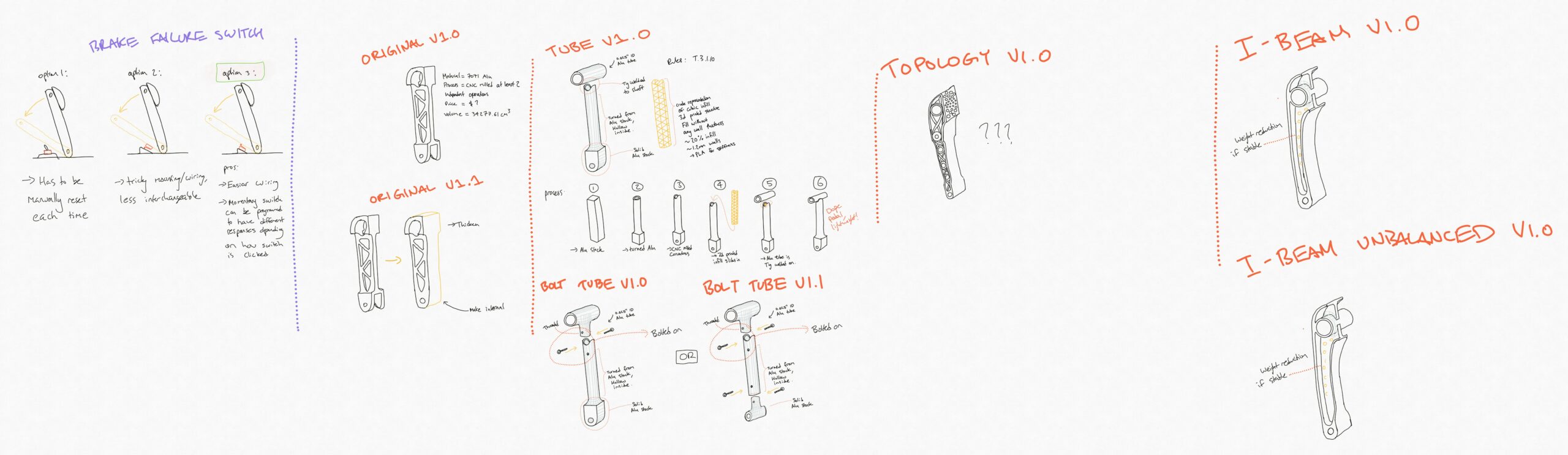
I assessed the above concepts using a weighted decision matrix where the criteria and weighting breakdown was as follows:
| torsional maximum displacement | mass | number of cnc machining operations / number of manual operations | potential for failure during machining (1-3, 3 being high) |
| 45% | 30% | 15% | 10% |
I proceeded with version “original v1.1” above after modelling several options and performing FEA as well as figuring out the machining operations for each option. Design development heavily leveraged simulation data since the load case is clearly defined in FSAE rules, so I was able to iteratively increase stiffness and shave off weight using SolidWorks FEA suite.
Here is a summery of the old vs. new designs, with simulations to compare stress concentrations as well as displacements under off-axis loading:
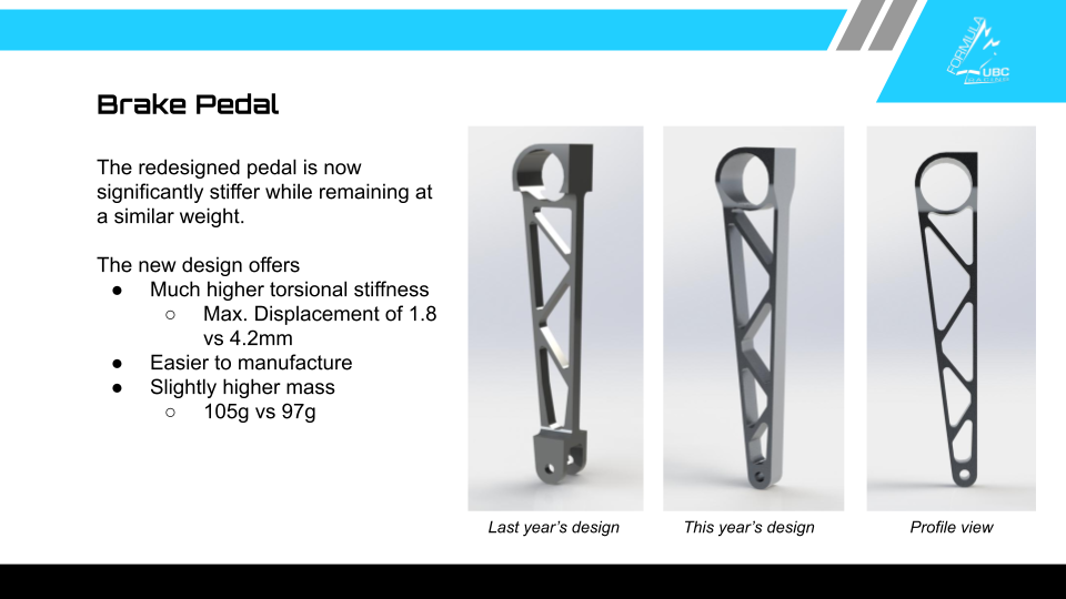
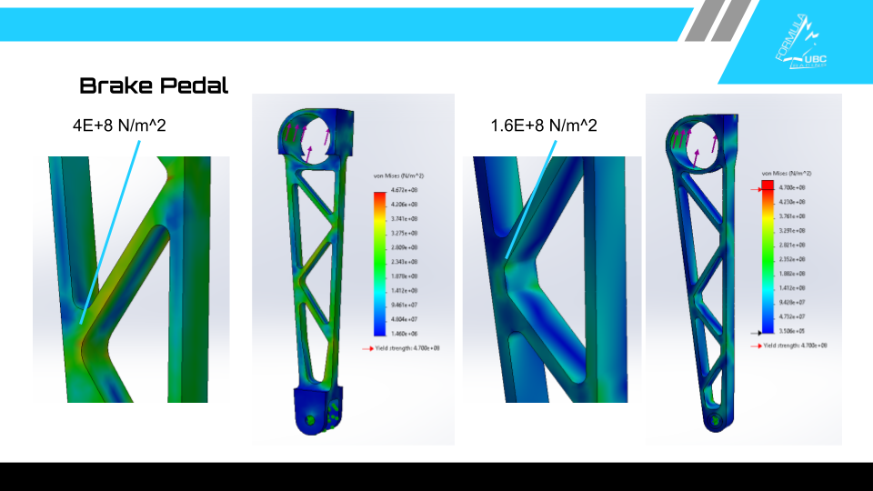
The guiding principles here were to increase the polar moment of inertia of the pedal’s cross section under torsion, minimize unstressed material, and simplify load pathing. As can be seen in the old design, the pedal’s structure is very narrow, which leads to poor performance in off-axis loading. The new design is about twice the width, and instead uses thinner gussets to save on weight. Also, the bottom of the old pedal was a bit of a mess, with very poor load pathing due to the celvis-like split and plenty of unstressed mass. The new design minimizes this mass and keeps the load path from the base mount to the master cylinder balance bar mount at the top straight.
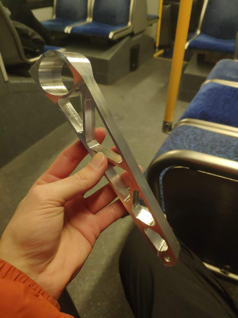
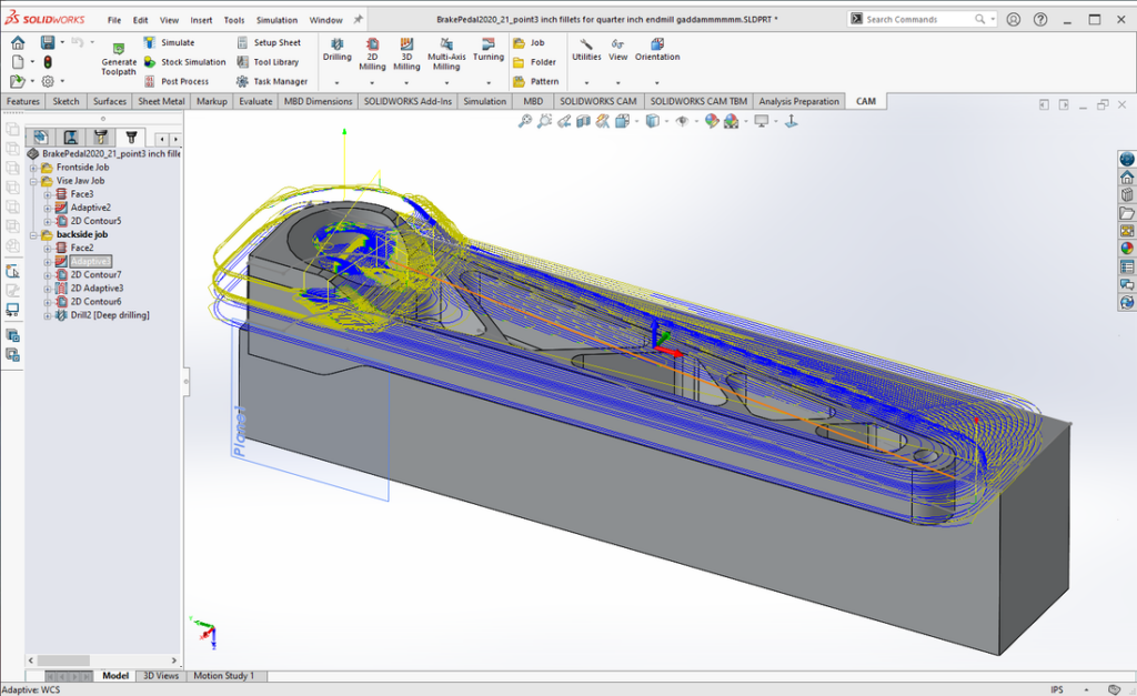
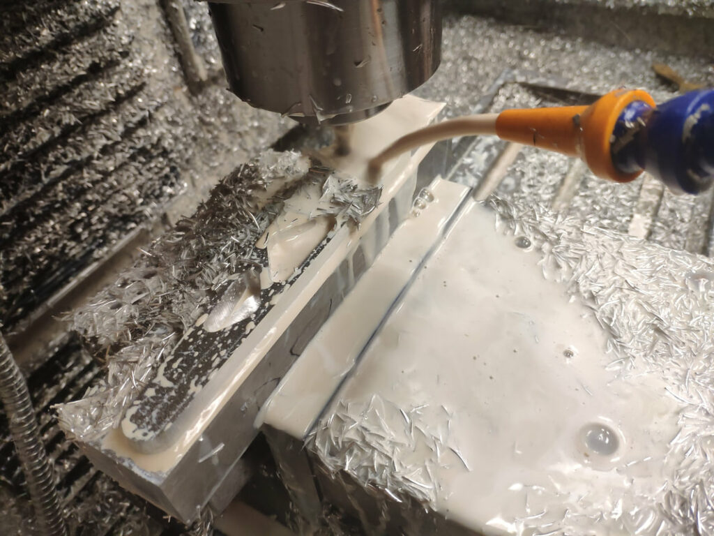
The following year after school returned to in-person, I began work on machining the pedal. Here are the HSMworks toolpaths I created and some photos of me machining it. I machined the pedal in three operations: First half, then I machined a custom vise jaw to locate pedal in x, y, and z, and finally the second half to machine away all the non-pedal metal:
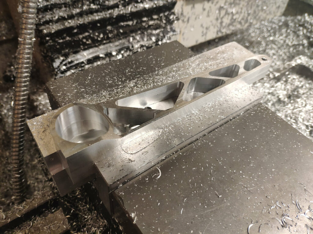
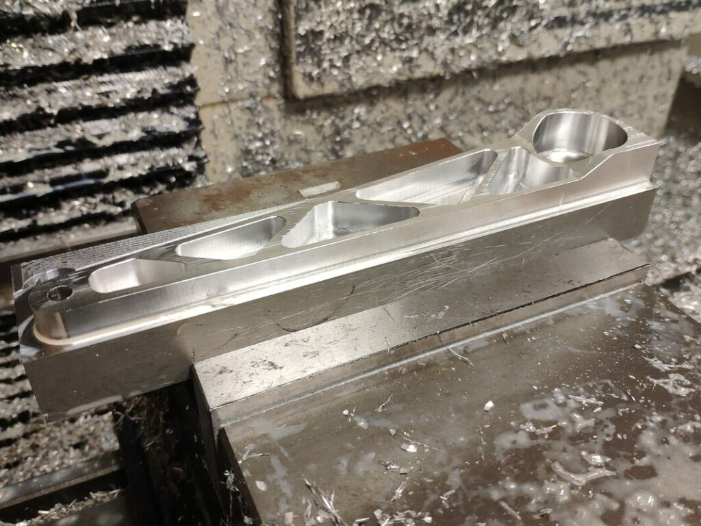
Here’s how the vise jaw I machined works:
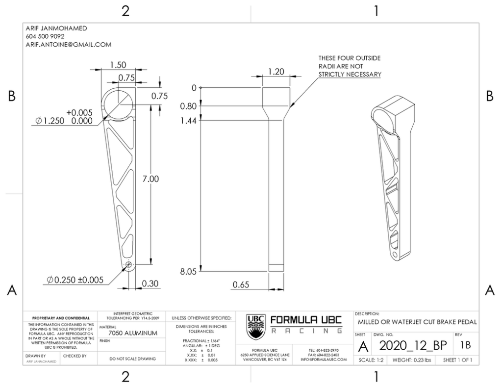
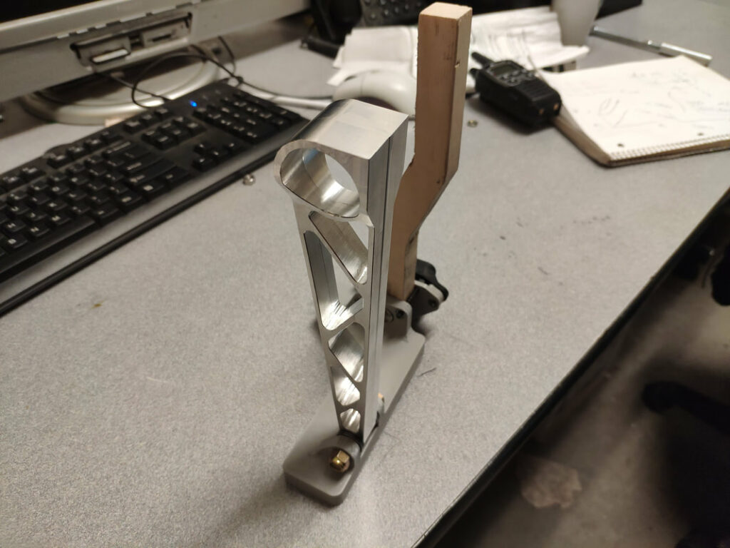
We ended up reusing the 2019 pedalbox in our 2021 car, so I machined a second version of this pedal that fit the same clevis-style mounting as the previous pedal. We then used this design for both a prototype Drive-by-Wire pedalbox that I designed for the 2023 car, as well as the final 2023 monocoque pedalbox! In all cases, we validated performance by preloading the pedal face with ~2200N after installation. Here you can see my engineering drawing, along with the pedal mounted on the prototype DBW pedalbox I made:

Design Outcomes
Minimal
weight gain
233%
greater torsional stiffness
60%
Lower stress concentrations
Skills and Learning
••••◦
Solid mechanics and design optimization for targeting stresses efficiently
••••◦
SolidWorks FEA, hand calculations to validate designs
••••◦
DFMA
••••◦
CNC machining and workholding
Leave a Reply