
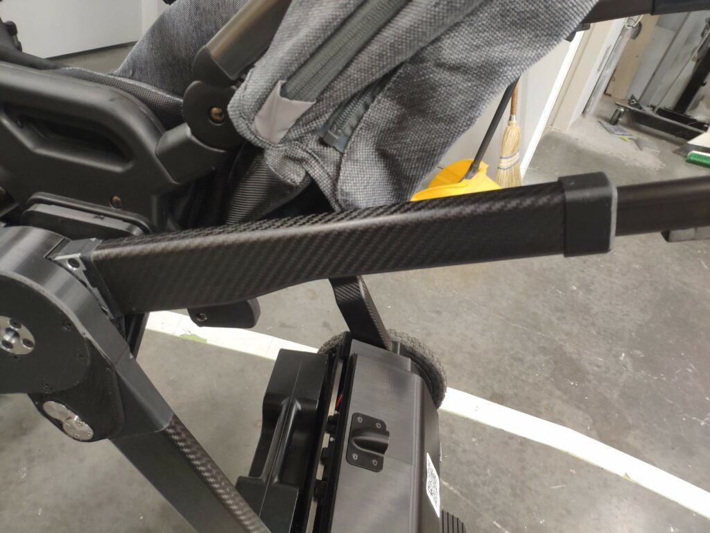
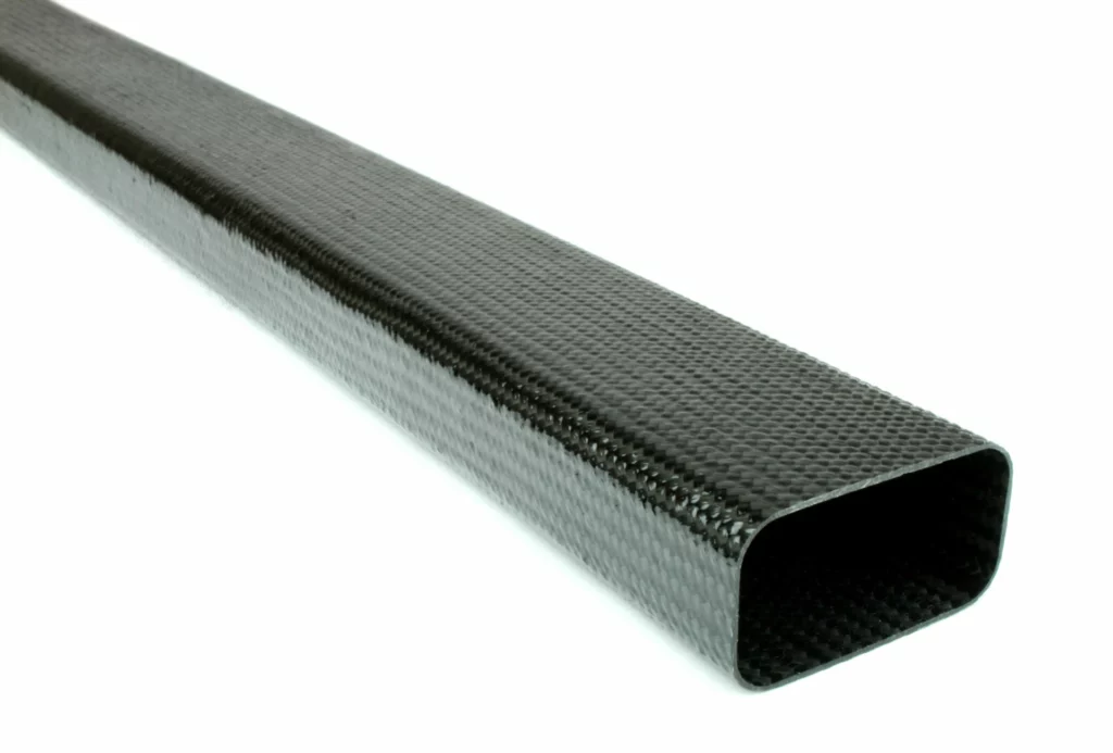
Before my time at the company, several UBC students had designed and produced molds and cured prepreg carbon fiber frame components for Ella, using bladder-molded machined aluminum molds. GluxKind wanted to evaluate the feasibility of using off-the-shelf pultruded and roll-wrapped carbon fiber tubing instead, and I set out to find some answers.
Indeed, OTS tubes required no upfront tooling cost, and though generally less performant, are very mechanically consistent (important when dealing with safety-critical applications!)
These were my goals:
- Characterize the buckling strength of OTS Pultruded Carbon Fiber in frame nominal sizes
- Characterize the impact of adhesive type and bonding technique of CF tube to plastic mounting inserts
- Understand the effects of fiber orientation on our load cases
To better understand the strength requirements of the frame, I started with some hand calculations of the main stressed frame members to get a baseline understanding of stresses the frame endures.
I then began researching different carbon fiber tubing options, while utilizing composites background knowledge from my work on Formula UBC Racing. I understood and quantified the differences between pultruded and roll-wrapped, prepreg and vacuum-infusion processes, fiber types, strengths and stiffnesses, etc.
I also did research on fiber orientation and layup schedules for torsional, bending, compressive, and tensile loads through tubes, seeking to understand how fiber orientation affects stiffnesses and strengths in these load cases. I also started understanding concepts like hoop stress and
At the time the company had previously purchased extra 1″ x 2″ pultruded carbon fiber tubing that they were interested in comparing against their previously-tested in-house-made bladder molded prepreg layups of the stroller’s frame. The person who’d worked on quantifying the house-made layups had identified the importance of impact strength in our application as well, and so I proceeded with my plan to test these two characteristics of the pultruded tube.
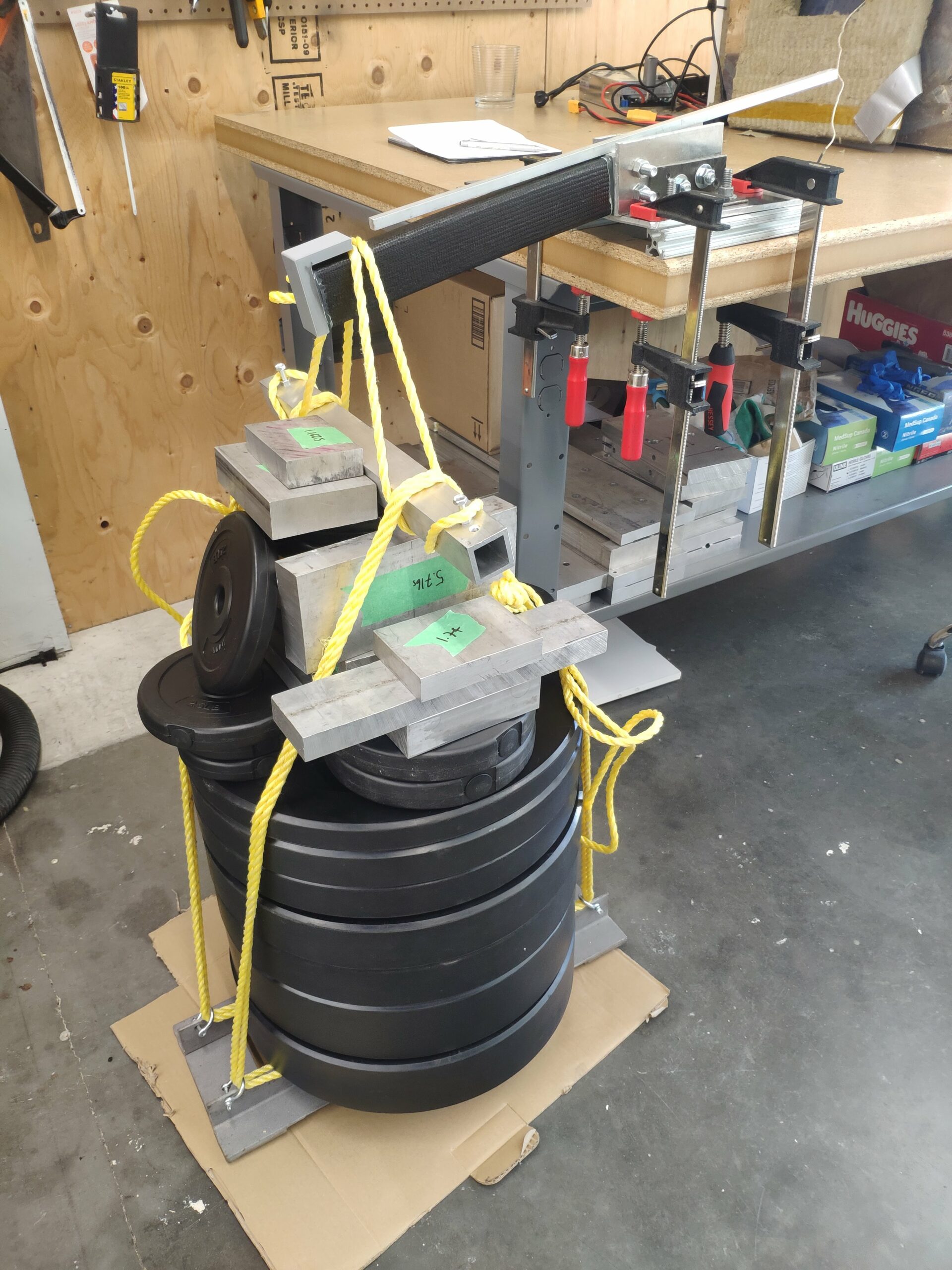
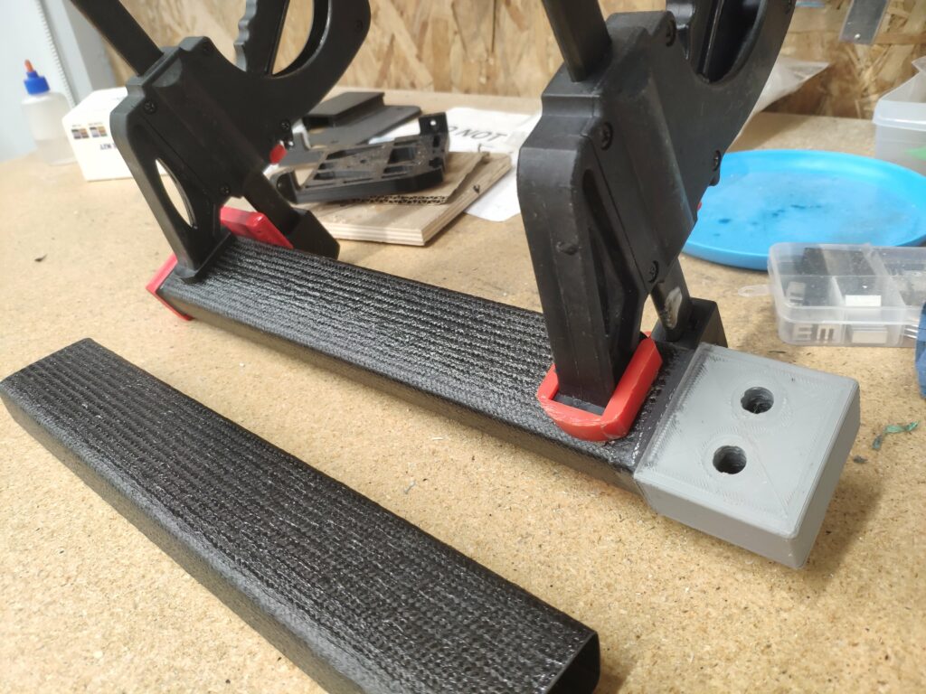
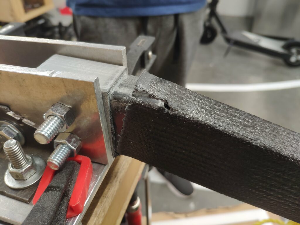
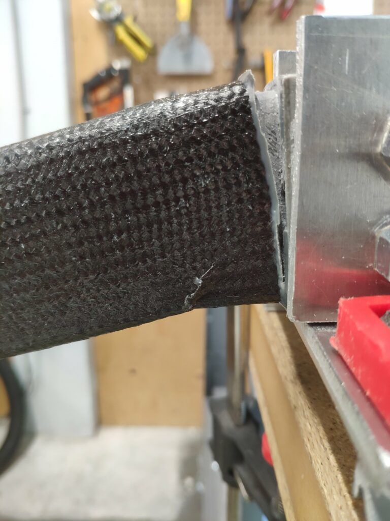
I modified the jigs that had been used for the prior tests to fit this new tubing, and designed and printed plastic inserts for either end of the tube to emulate the actual printed plastic joint parts on the stroller. These were essential to represent the stresses in the frame member, because the solid plastic insert greatly increases the hoop strength of the insert-carbon-insert member, reducing susceptibility to buckling and crushing (though I hadn’t heard these terms yet in school, i began to understand concepts like hoop stress and buckling strength). I designed the inserts to have a two inch thick ring of surface area contact with the interior of the carbon tube in order to maximize bond area and thus try to reduce the stress concentrations present in transferring stress between the tube and the insert.

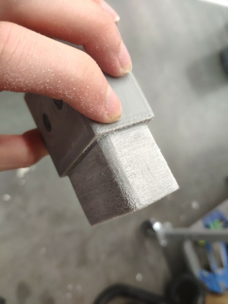
I sanded the inserts really well as well as scuffed the interiors of the tubes. As I was reading (and would later learn at school!), roughening the surfaces raises their surface energy and thus leads to better wetting of the adhesive between them. I washed, dried, and bonded the surfaces with JB-weld. This was the same procedure followed when testing the in-house layups.
Well, clearly I didn’t scuff enough!
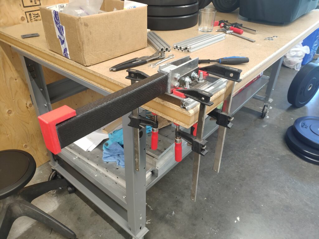
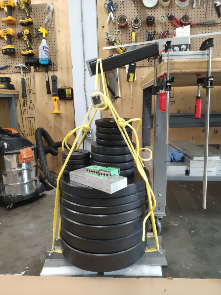
I verry-rigged a platform to hold weights and used this to increase the bending stress in the tube:
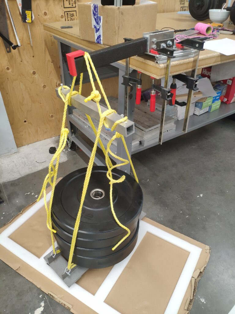
The tube failed at a lower weight than expected, and split open at the top corner at the grey insert. This behaviour, combined with the fact that all the adhesive remained adhered to the plastic insert, suggested to me that our adhesive was not bonding well enough to our carbon fiber, and thus the composite system of the insert-carbon-insert was not performing optimally.
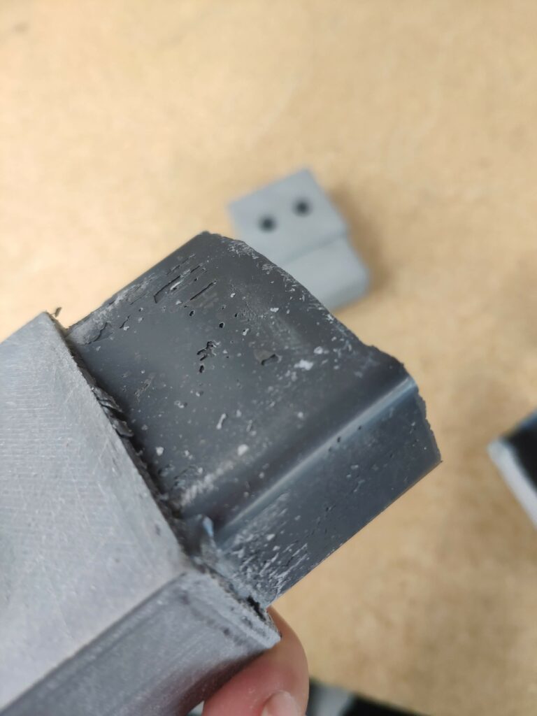
I also noticed that the adhesive was quite flaky, and could be crumbled with my nails. I suggested to the team that this behaviour suggests JB weld is a poor choice for the joint, and we should try to select something with better toughness and ensure good bond shear strength.
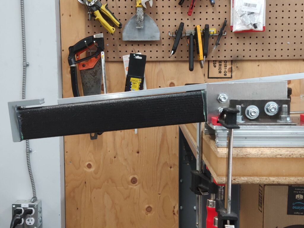
Next test, I sanded the interior tube faces much more, and also decided to try curing the adhesive for a few days. I added a flat bar using the insert face as a reference with which to better understand bending stiffness as well, tracking tube-bar displacement. I used a new 3M engineering adhesive that we got for this purpose based on my prior concerns.
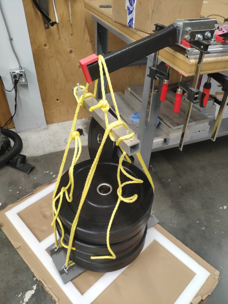
This time, the tube took nearly double the weight to fail, and failed in a different mode: buckling of the bottom corners and bond failure at the top:
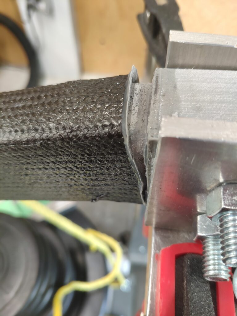
This was much more in line with my expectations, and the buckling behaviour made sense given my understanding of carbon fiber’s relative weakness in compression.
But I still felt that the bond strength could be improved, and so I trialed a third time , waiting a full week for the adhesive to cure based on some reading about how what I thought was a minor difference between the datasheet’s cure temperature and ours was actually quite significant, and our sample could take much longer to cure fully.
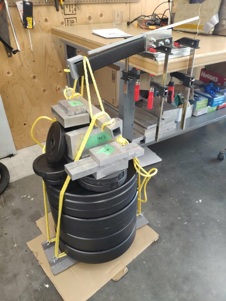
This time, it took everything I could weigh and fit on the sled, and still did not fail. It also experienced less deflection relative to prior tests, suggesting the bond stayed rigid for longer. When I say everything, I mean it. I ended up standing on top of this whole stack and the tube still didn’t fail.
After removing the weight, I wanted to check for any plastic deformation, but found none using my initial reference bar for straightness:
In the end, it was clear that waiting long enough for a proper cure at the cure temperature was critical, that tougher high shear strength epoxies were very effective in this case, and proper surface preparation was very impactful.
| Variable | Trial 1 | Trial 2 | Trial 3 |
|---|---|---|---|
| Surface prep | Insufficient abrasion | Significant abrasion | Significant abrasion |
| Adhesive | Brittle JB-Weld | Tough 3M | Tough 3M |
| Cure time | 1 day | 3 days | 7 days |
| Failure load | 175lb | 283lbs | 369lbs |
| Stiffness | unmeasured | 18.2mm @280lb | 16.3mm @280lb |
Puncture resistance remained relatively constant across the three trials.
Compared to our in-house layups, these were stronger when tested with appropriate adhesive, cure time, and surface prep.
Design Outcomes
111%
Improvement in failure load
11%
Reduction in displacement at constant load
+
Greater strength than out in-house layups after process refinement
Skills and Learning
• • • • ◦
Materials Science
• • • ◦ ◦
composite failure modes
• • • ◦ ◦
composites general learning
Leave a Reply