
About a month into my four-month internship, I began phase 1 of overhauling Ella’s handlebar design.
My phase 1 design objectives were to:
- improve ergonomics
- reduce cross-sectional area
- incorporate two load cells for pushing force detection
- Incorporate digital RGB LEDs to provide rich communication with the parent in autonomous mode
- Incorporate haptic feedback
- Incorporate a physical autonomy toggle and rear camera for parent facial and gestural recognition
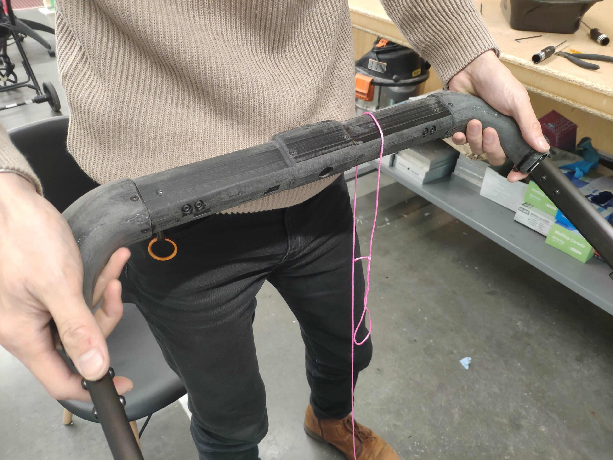
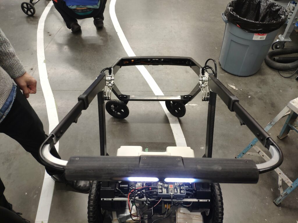
Here I am trying to get a sense for how it would feel to hold. I ended up walking to a local baby store and trying out a bunch of normal stroller handlebars to get a sense for comfort and the feeling of security a handlebar should give you.
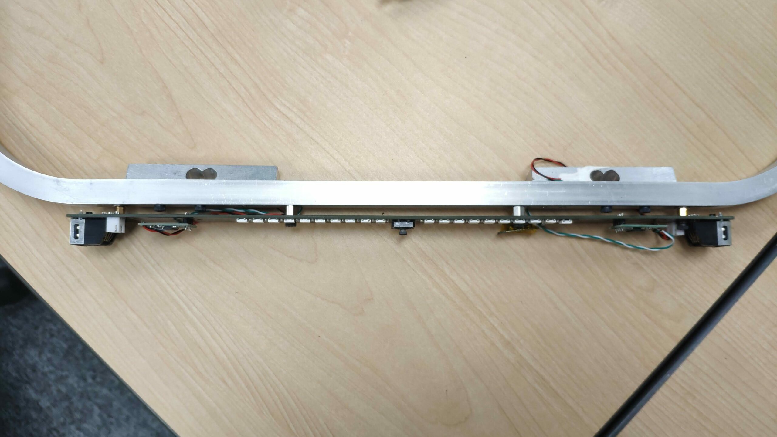
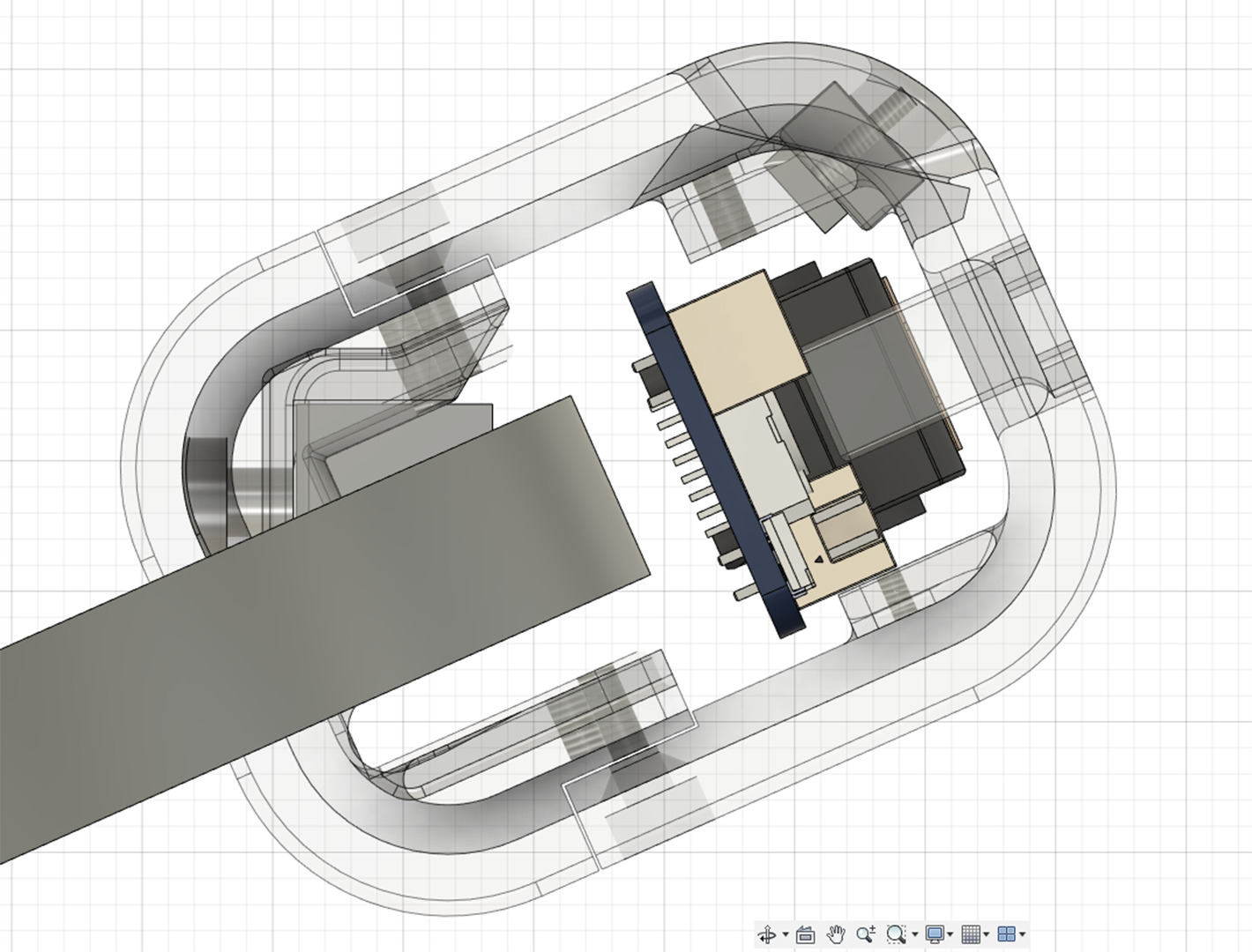
I pursued a two-piece shell design which integrated our existing handlebar PCB while shifting several of the SMD and THT components on the pcb from the front to the back. Pictured below is the previous PCB with components all mounted on the front. As seen, the dual RJ45 connectors on either end take up a ton of space. I soldered new PCBs without the RJ45s, shifted the button onto an additional board which sat at the back of the handlebar, and swapped the lead cell amplifiers around to the back.
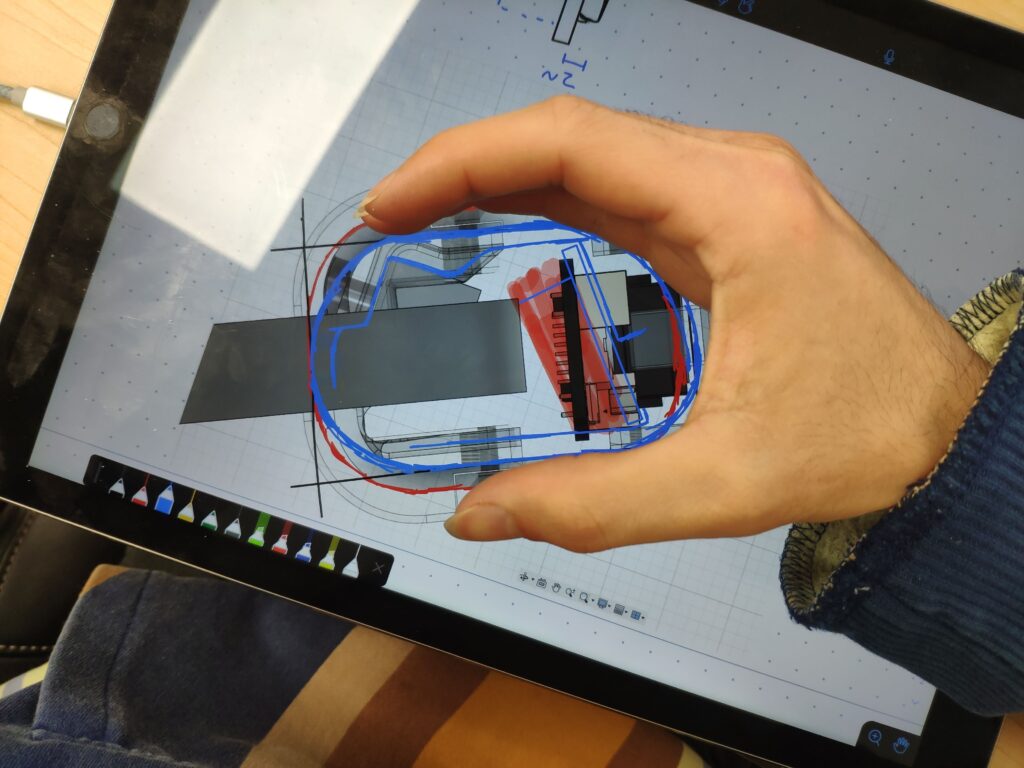
The goal of this was to push the PCB closer to the edge of the front enclosure to both create space and bring those LEDs more within view:
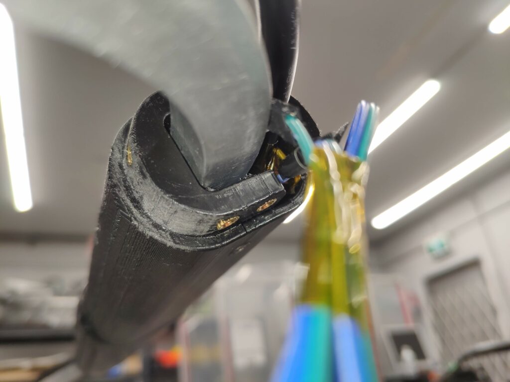
But we can’t have great big holes in the handlebar. So I came up with the idea to cast the holes in clear resin that we already had on hand and sand off to create a diffuser for the LEDs:
This solution ended up being pretty much perfect for our rapid prototyping needs, and the company even ended up sticking with it long-term!
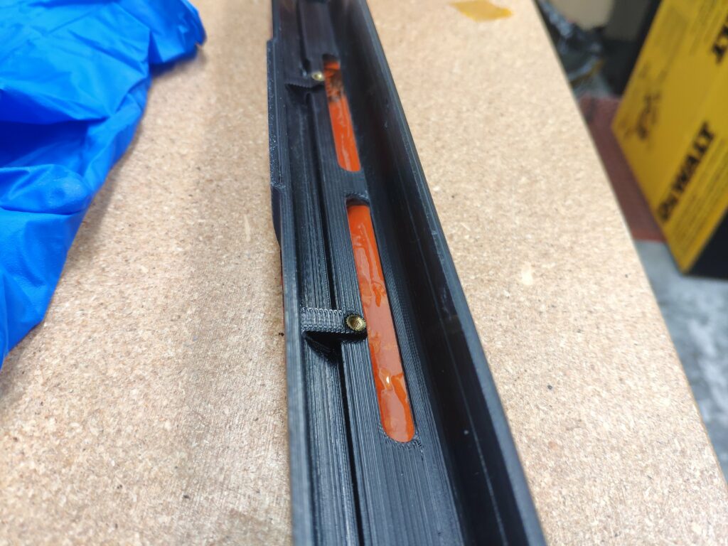
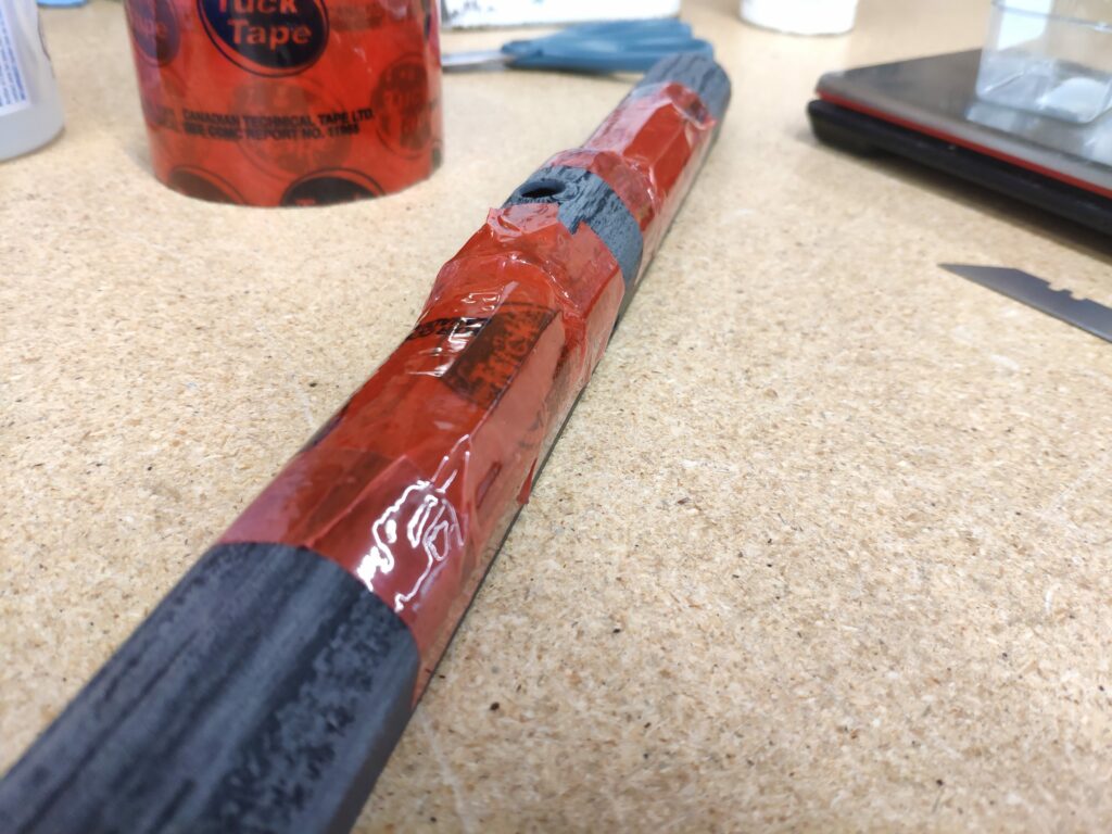
Above you can see the resin curing inside the windows, with some tape to seal create a pocket for the resin to sit (later removed). You can also see the threaded inserts I switched to as all previous designs were just tapping straight into the 3d printed plastic and unfortunately this was not very tolerant of more than one assembly 🙂
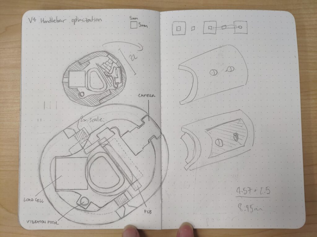
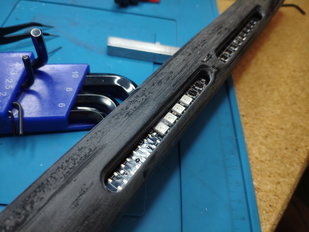
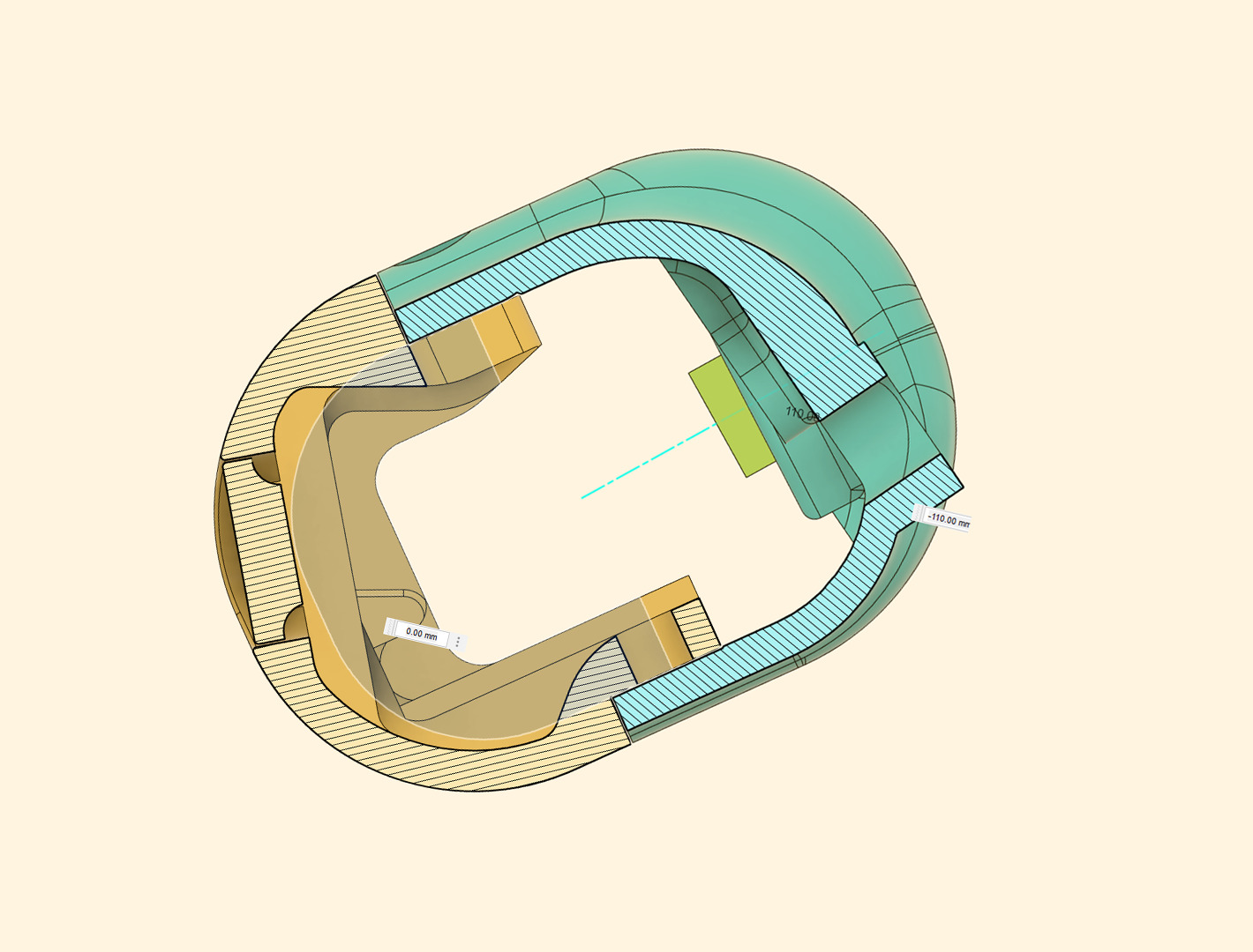
Here is a comparison of the cross sections of old and new designs, and some photos of assembling the enclosure pieces and testing out some of the LEDs:
The five revisions of this design that I produced and tested greatly improved my CAD skills in Fusion 360, and I got some great practice using a ton of sweeps and lofts. All revisions were printed, assembled, and tested by myself.
A challenge was designing the whole enclosure in a way that it did not interfere with the load cells’ ability to gather reliable data. We had problems with Load cell hysteresis that caused the motors to not fully stop when the handlebar was let go, so we needed to address this.
We approached it by both adjusting the load cell “deadzone” and by swapping to a less exothermic resin for the windows. The exothermic cure reaction of our resin was causing some warpage in the enclosure, which induced some stresses onto the load cells at rest, which I discovered by tightening and loosening the mounting bolts for the cells.

In the second phase of this design, I focused on:
- DFMA-focused design refinement using:
- Injection molding
- Aluminum tube hydroforming
- Collaborating with our Electrical Engineering Intern to redesign our PCB to be more compact and optimized for this new design.
- Implementing a cooling solution for interior handlebar PCB
I researched these different manufacturing processes, understood their limitations, and refined my design to be made from 2 injection molded pieces, each made in a two-part mold. The design used 10 fasteners.
This is a reduction from 6 3d printed components and 18 fasteners.
Next, we were finding that too much heat was being generated from the LEDs and VRMs on the PCB for the plastic enclosure. Thus, I needed to develop a solution for thermal dissipation.
I ended up modifying our PCB design to use thermal vias and a bare copper back face mounts directly to our aluminum handlebar internal structure, transferring heat through conduction to the sides of the handlebar, where it can escape into the surrounding air. The aluminum handlebar structure also has a significant enough thermal mass to regulate these temperatures well without adding any bulk to the handlebar.
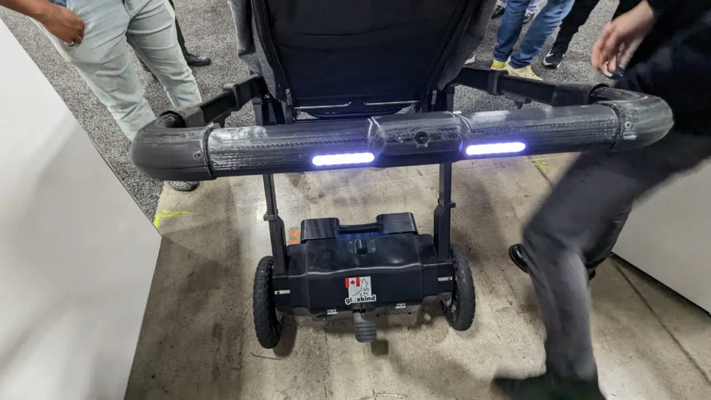
Two months after I finished my internship, GluxKind travelled to CES in Las Vegas to show off our design, and we won a CES Innovation Award!
Design Outcomes
100%
Improvement in positive ergonomic feedback
35%
Reduction in cross-sectional area
67%
Reduction in handlebar enclosure components
46%
Reduction in handlebar enclosure fasteners
All
Targeted features incorporated
Skills and Learning
••••◦
Mechanical Design
•••◦◦
Electrical Design
••••◦
DFMA
••••◦
Ergonomics
•••◦◦
Thermal Design
Leave a Reply