
A central feature of my degree in Integrated Engineering is our annual capstone design project. This 5-6 person team project takes the place of a course in both first and second term, and the best part is that each and every student has the opportunity to develop their own idea for a project and pitch it to the whole class.
For the second year in a row, my project pitch was voted as a top 10 project out of 60 pitches, and I was lucky enough to form a great 5-person team around the project. Several of my classmates with experience on UBC’s design teams, including Formula UBC (my own team!), UBC Rocket, and UBC Baja SAE joined the team.
Below is a summary of the project and work done, but if you’d like to read further, you can download our full project report at the end of this page.
Project ReMold aims to reduce the financial and physical waste, long lead times, and frustrating storage problems inherent to CFRP and GFRP composites manufacturing, all of which come from molds! Traditionally, molds are slowly machined out of aluminum or foam blocks at great expense on a CNC router which is usually operated by an external shop. This process is very wasteful, as often the majority of the material gets landfilled, especially in the case of foam (the cheaper option). This process can take weeks to months when dealing with shop lead times, and if anything about the design changes, well you’ve usually got to throw the whole thing out and make a new mold. And once your mold is used for layup, you’ve got to store it somewhere – who has space? Think about how inaccessible this all is to a small student design team, or a startup working on product prototyping. Even for businesses doing composites repair, like fiberglass marine and aircraft body panel replacement and repair, this process makes the barrier to entry so high.
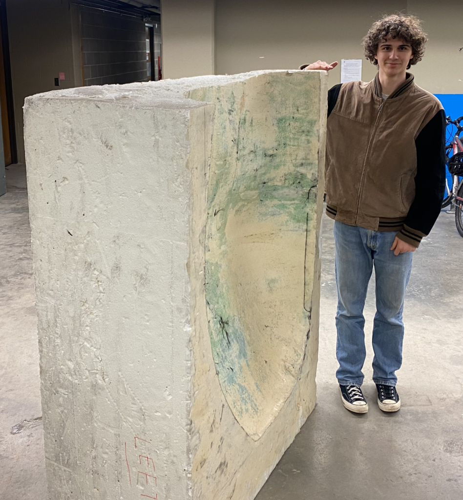
Here’s my teammate Evan next to one of the massive foam molds we found while walking around campus!
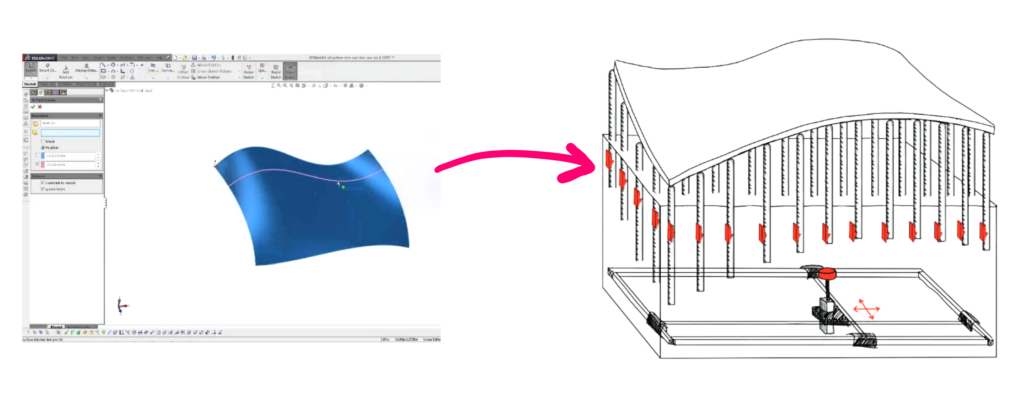
Project ReMold takes a completely different approach to composites moldmaking, instead using a flexible mold surface which can adapt to suit a variety of shapes depending on the user’s CAD model. You upload the surface you want the mold to take the shape of, wait less than 2 hours, and ReMold will have reconfigured itself. Need to make an adjustment? No problem – the tool can quickly adjust it’s surface geometry without needing to replace anything. And when you’re done, you can reset the surface without worrying about mold storage. This product is ideal for low-volume composites manufacturers who deal with custom one-off designs frequently. Our student design teams, any business wanting to Prototype with composites and refine their designs, or composites repair specialists who need to produce all sorts of curved repair layups are perfect customers for ReMold.
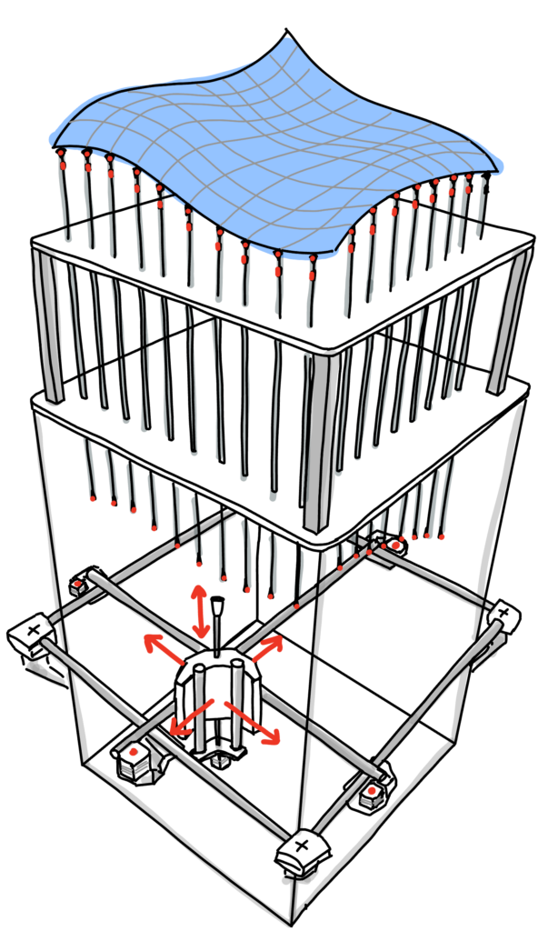
The initial design concept I developed was to use an array of pins whose height can be individually adjusted by a CNC gantry which lives beneath the machine. The gantry moves to each threaded pin and spins it to raise or lower, and then continues onto the next pin. Why a gantry instead of linear actuators? This design scales very well to larger sizes, because the expensive components are mostly in the gantry and not the cheap threaded rods. Making the gantry 6 inches longer is cheap compared to buying 20 new actuators!
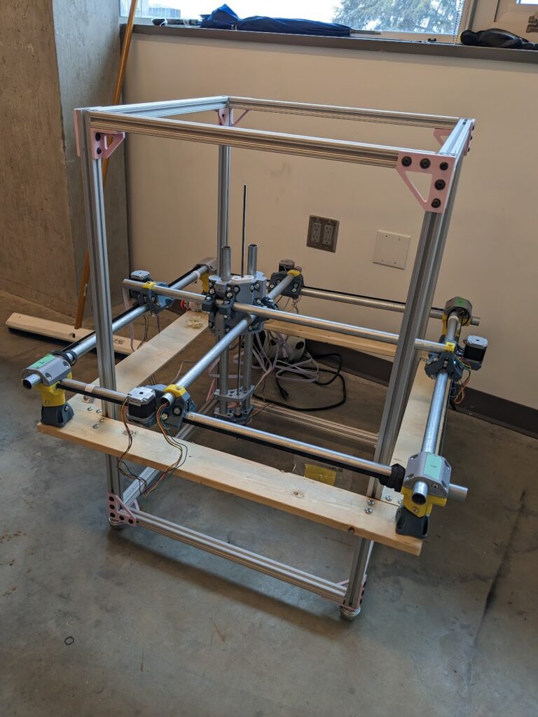
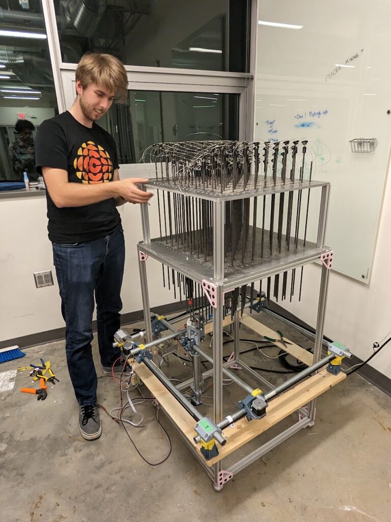
Operating as students on a small budget with a very ambitious idea, I led the team through development with a proof of concept approach. This tool is quite a bit smaller and lower-resolution than we’d hope it to be in a final use-case, but served our purposes well for development.
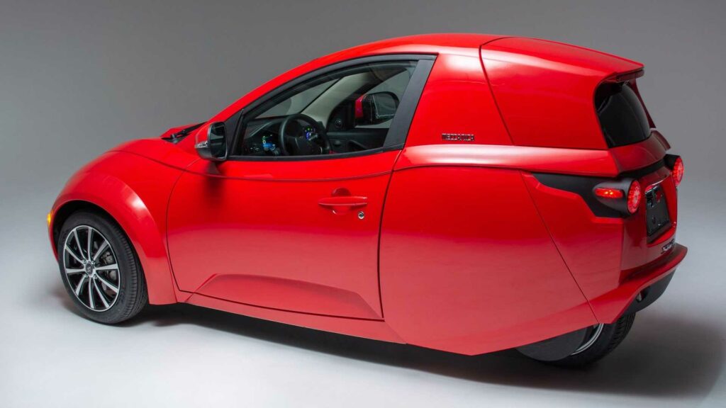
We spent time interviewing stakeholders like Henry Reisner, the owner of Intermeccanica, who has spent decades manufacturing GFRP auto body panels using machined molds, often having to do one-off parts with the development of the offshoot company ElectraMeccanica’s Solo vehicle. We involved Henry early on in the process and ended up speaking with several machinists in the Vancouver area who manufacture these molds for Henry and others. We also sought applications in many of the composites manufacturing that our student teams do here on campus (auto wing elements, body panels, underbodies, rocket nosecones…), and gained support from various team leads in our community. Support for the project from these stakeholders allowed us to prepare an application for grant sponsorship from UBC’s Sustainable Projects Fund for $2000, which I also successfully pitched and secured funding for the team!
Development was a long process so I will touch on some of our key testing and realizations that informed the rest of the project below:
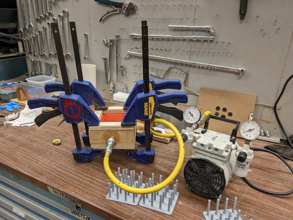
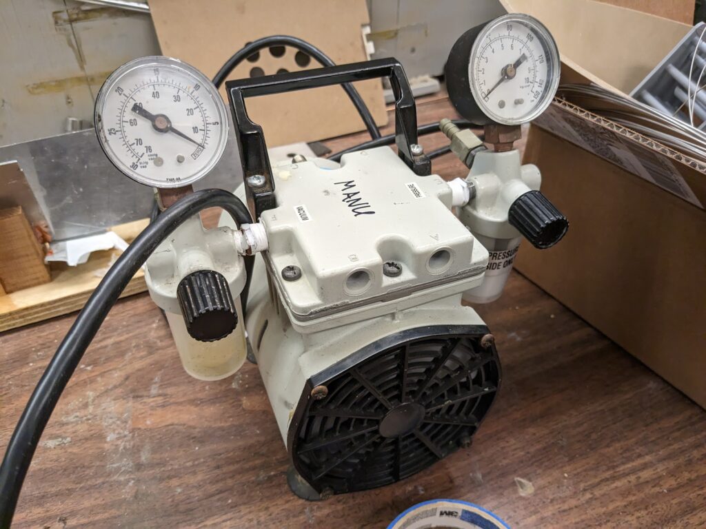
To test the pin concept, we created a series of 3D prints to simulate various surfaces. We knew that composite layups need smooth, contiguous, watertight, and temperature-resistant surfaces, so we imagined a silicone sheet which would adapt to the pins via applying vacuum to the underside where the pins are, effectively sucking the silicone down onto the pins. Here you can see how we tested this concept:
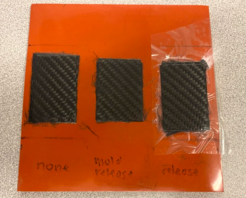
We tested different mold release strategies using this surface on some carbon fiber donated to our project by UBC’s Composites Research Network, and determined that release film yielded our best results without the manual labor involved with mold release application.
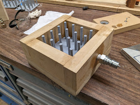
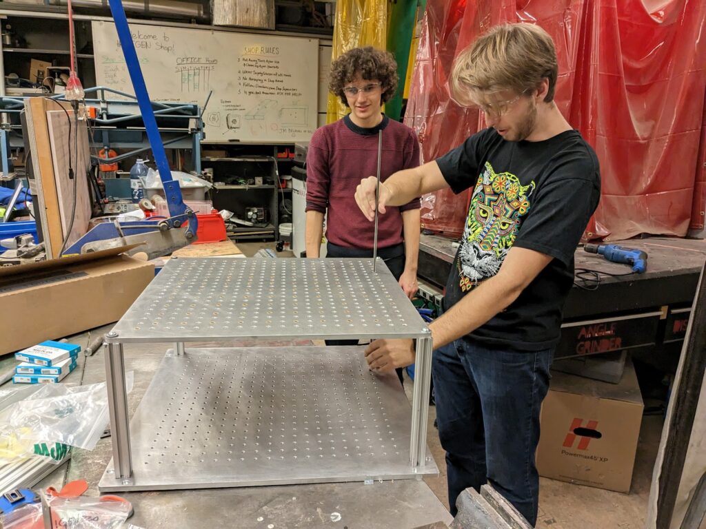
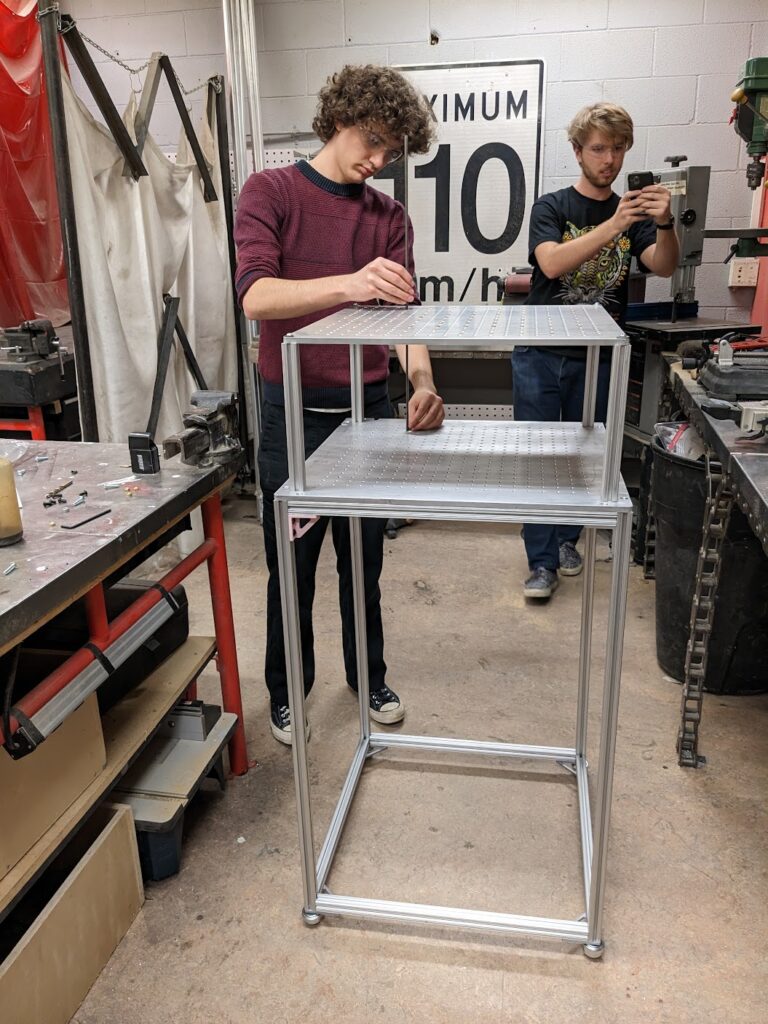
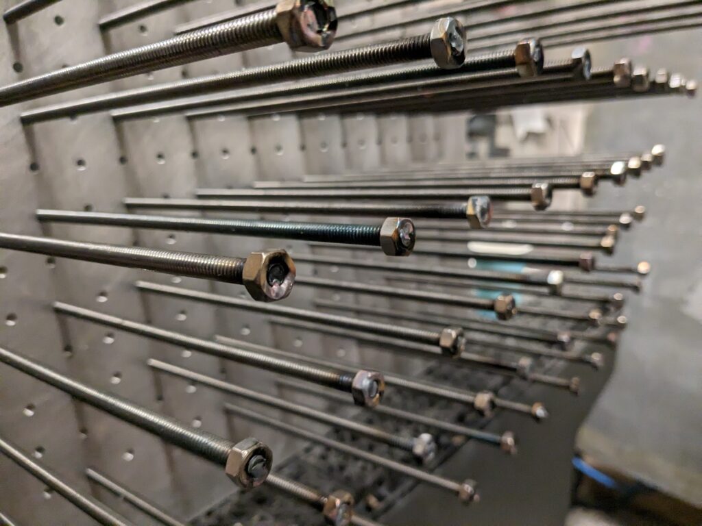
Now let’s take a look at the actual pin bed. We designed two plates, one steel plate with 1/4-20 threads, and one aluminum plate with press-fit bushings to support the rods against bending:
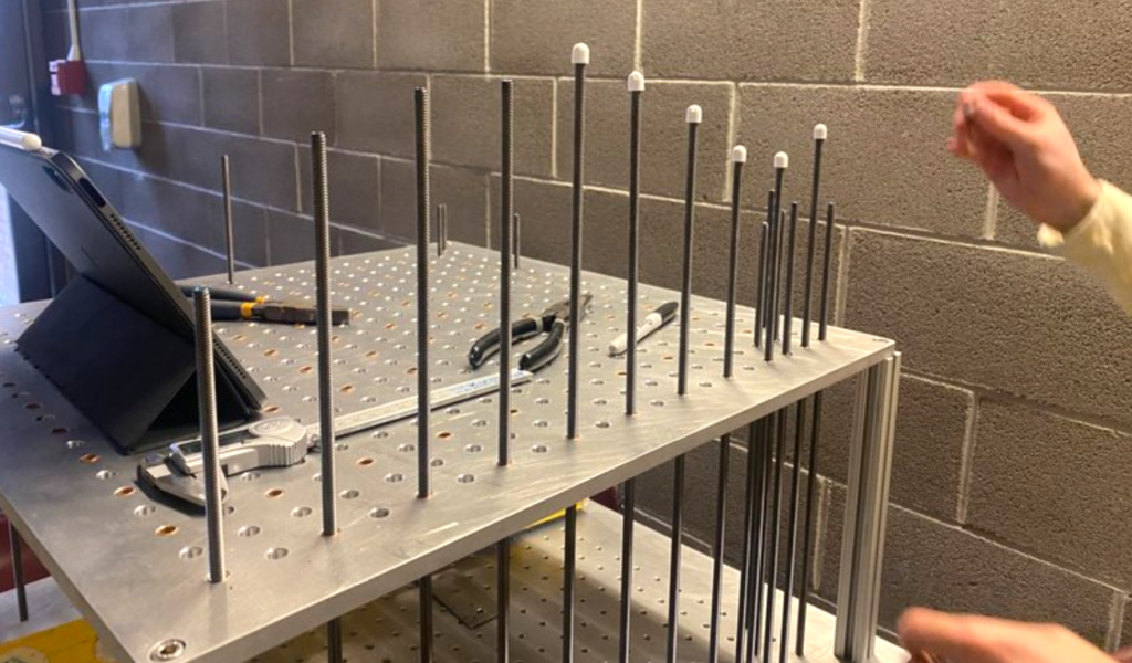
Above you can see us trying out some initial concepts for “pin heads” to interface between the threaded rod and top surface. We had many discussions and questions regarding this pin-surface interface:
Why not have the top silicone layer permanently attached to each pin? This was a source of much debate and thought for us. If the top surface is rigidly mounted to the pins, then it will have to stretch when the pins actuate. We knew this would require a much more robust structure, and would also produce “taut” surface geometry where subtle curves are virtually impossible. The vacuum idea was a way to overcome this, but so many other solutions were explored!
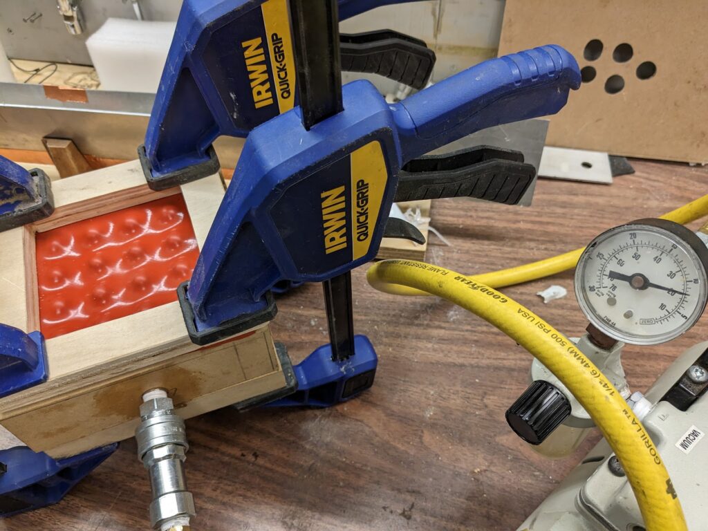
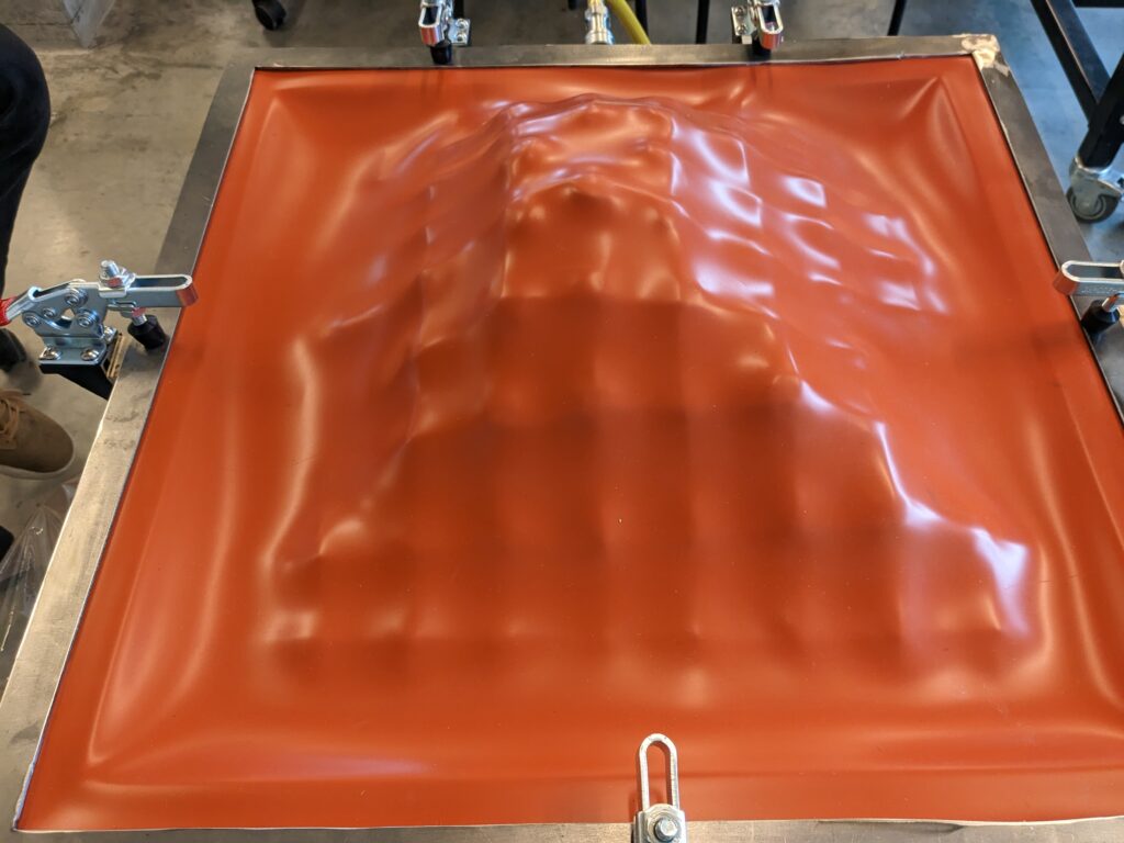
We found that the system critically needed some sort of support which could prevent the silicone from deforming so much around the pins. We also found that testing different durometers of silicone vastly changed the texture of the surface – too soft and the “waffling” would be extreme, too hard and the surface wouldn’t properly reach the low pins.
We determined that the best path forward was to use the low durometer silicone due to it’s ability to deform easily to the pin surface and strong temperature resistance over many cycles of use. However, it also exhibited the worst waffling, and so I came up with the idea to place structural wires across the pins to provide greater support. We then tested the concept with interstitial wires as well, and the result was so much better! The challenge was, how do we scale this system up in a way that each pin can still move relative to it’s adjacent pins while also remaining attached to these wires?
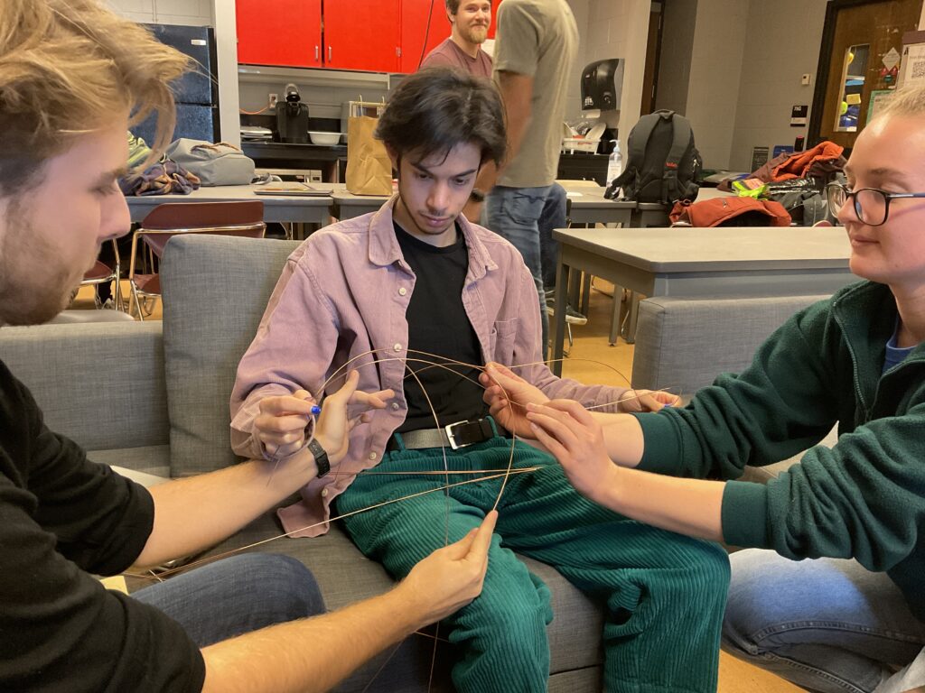
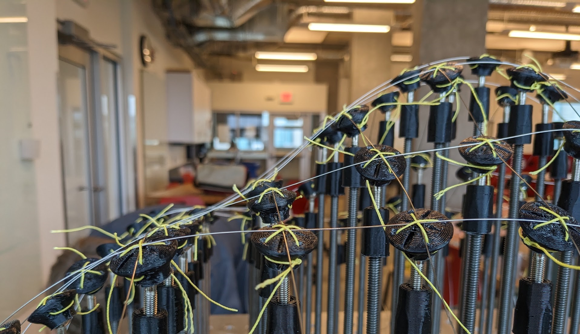
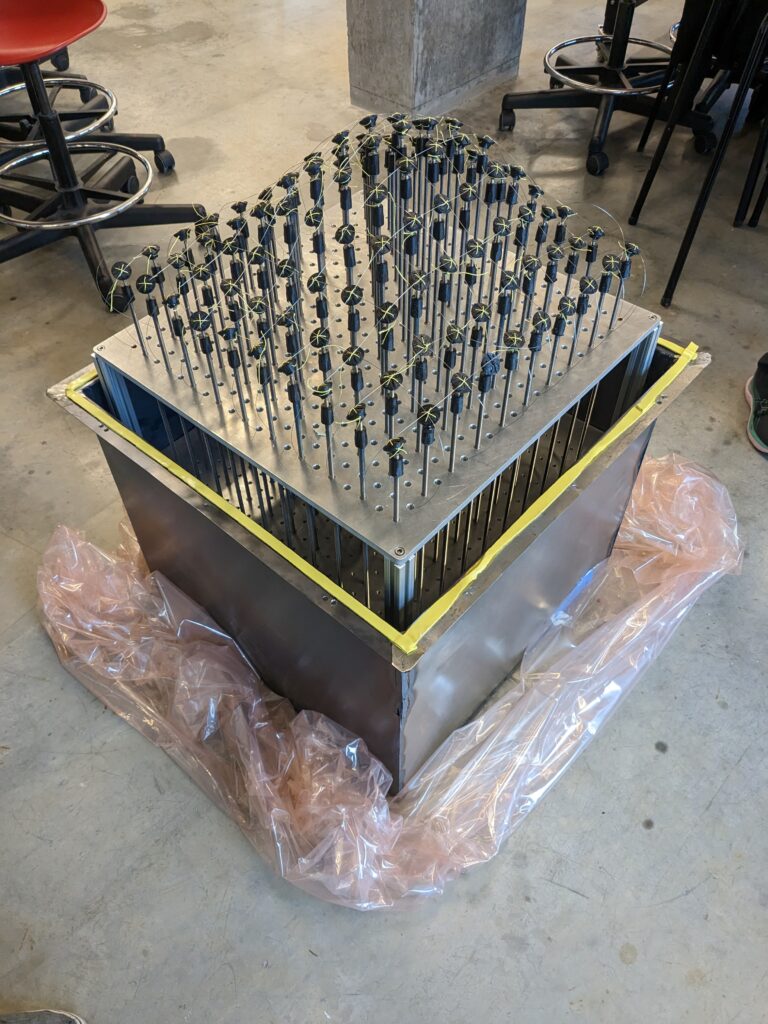
For this, I developed the “pin head” design, which aimed to support as many surface geometries as possible while allowing the wires to slide along each pin:
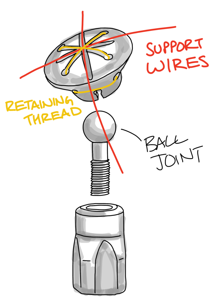
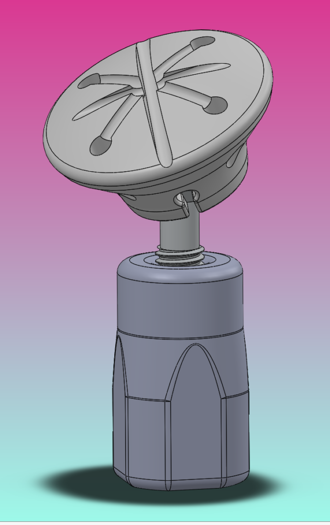
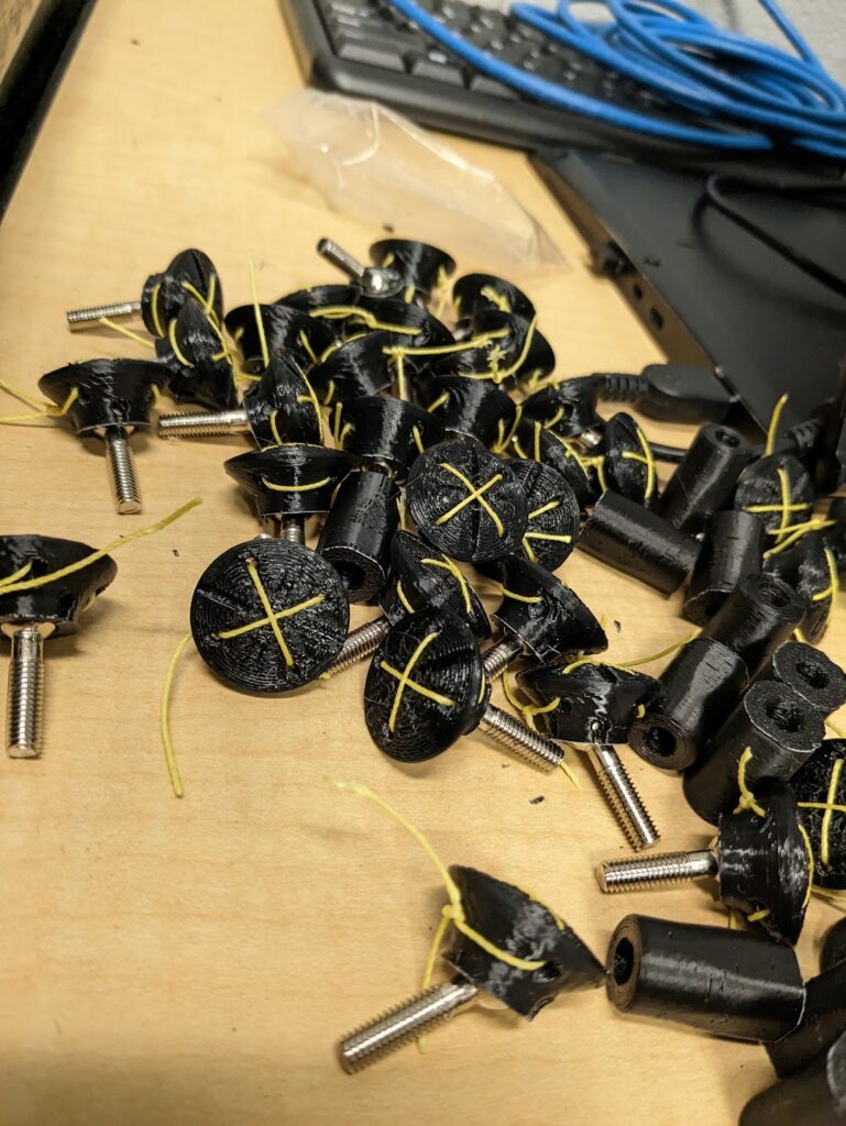
The design uses a huge pack of RC car axle ball joints I ordered off AliExpress, Kevlar string, and 3D Printed ASA parts to create a hundred pin head assemblies for each pin. The whole team pitched in to assemble and install all these guys!
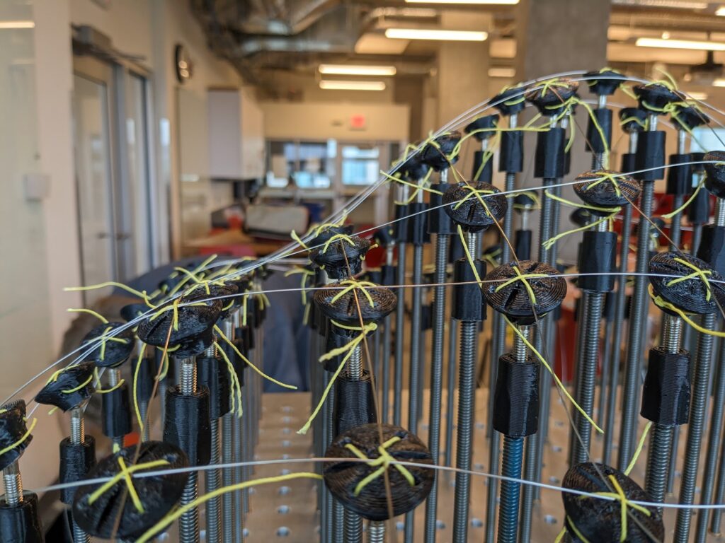
After installing and testing the “smoothed” surface geometry from the wire layer, I was extremely proud of the pinhead design and our work in bringing the concept to reality. Just look how well the ball joints and sliding wires work here!
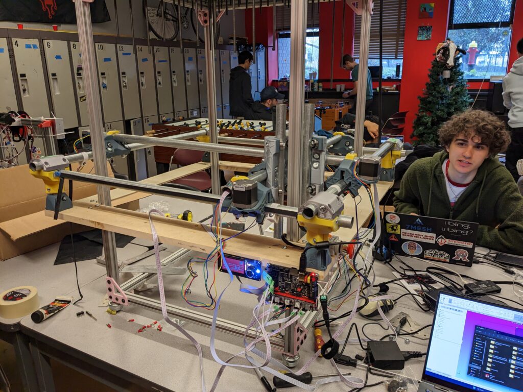
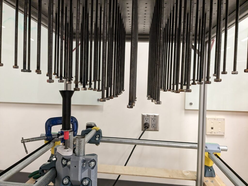
Next, we began work on the CNC system to actuate each pin automatically from below. Here you can see us adapting a CNC router I had previously built using the MPCNC open-source platform by inverting the Z axis and shortening the travel in x and y:
Work on the “grabber” mechanism to engage and disengage with each pin was probably the most challenging aspect of the project, and we still have not realized a a solution I was happy with. Here are some looks at the concepts discussed and the implementation. The challenge is that the actuator needs to rise, latch onto a pin, and then rotate it while translating up or down at the matching rate given the thread pitch of each pin. Additionally, this grabber has to be narrow enough to fit between pins without colliding.
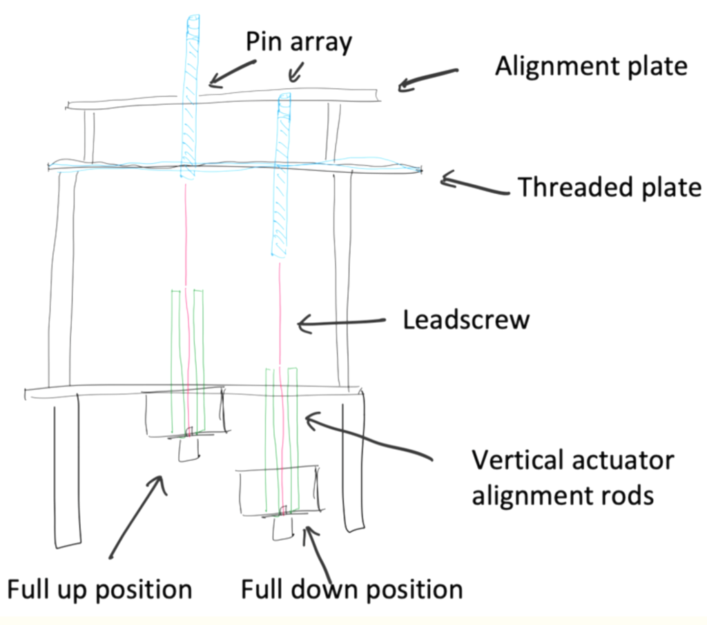
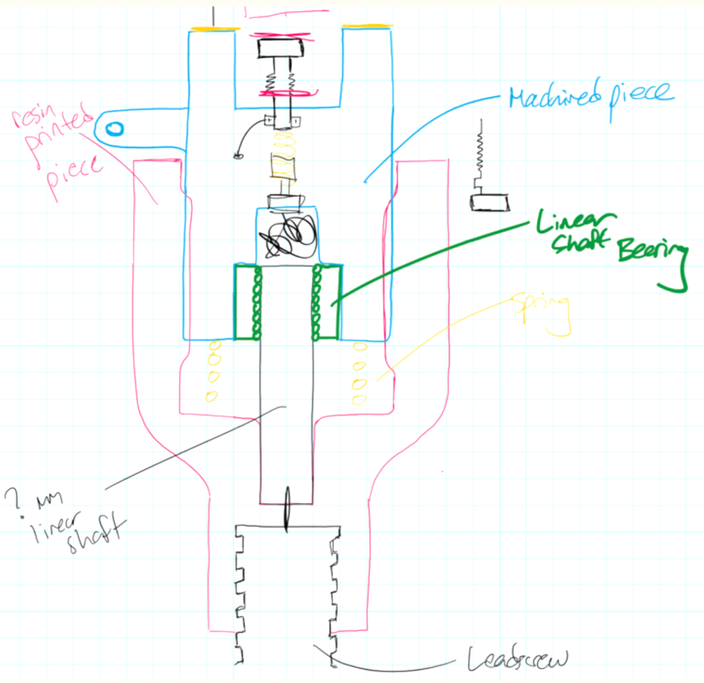
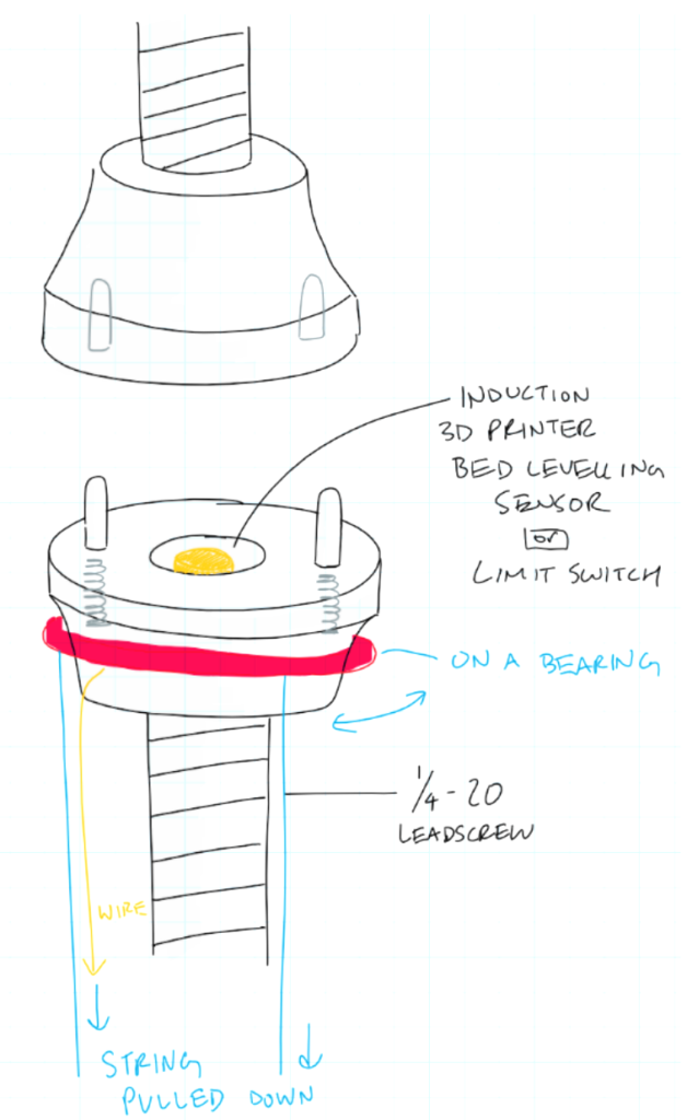
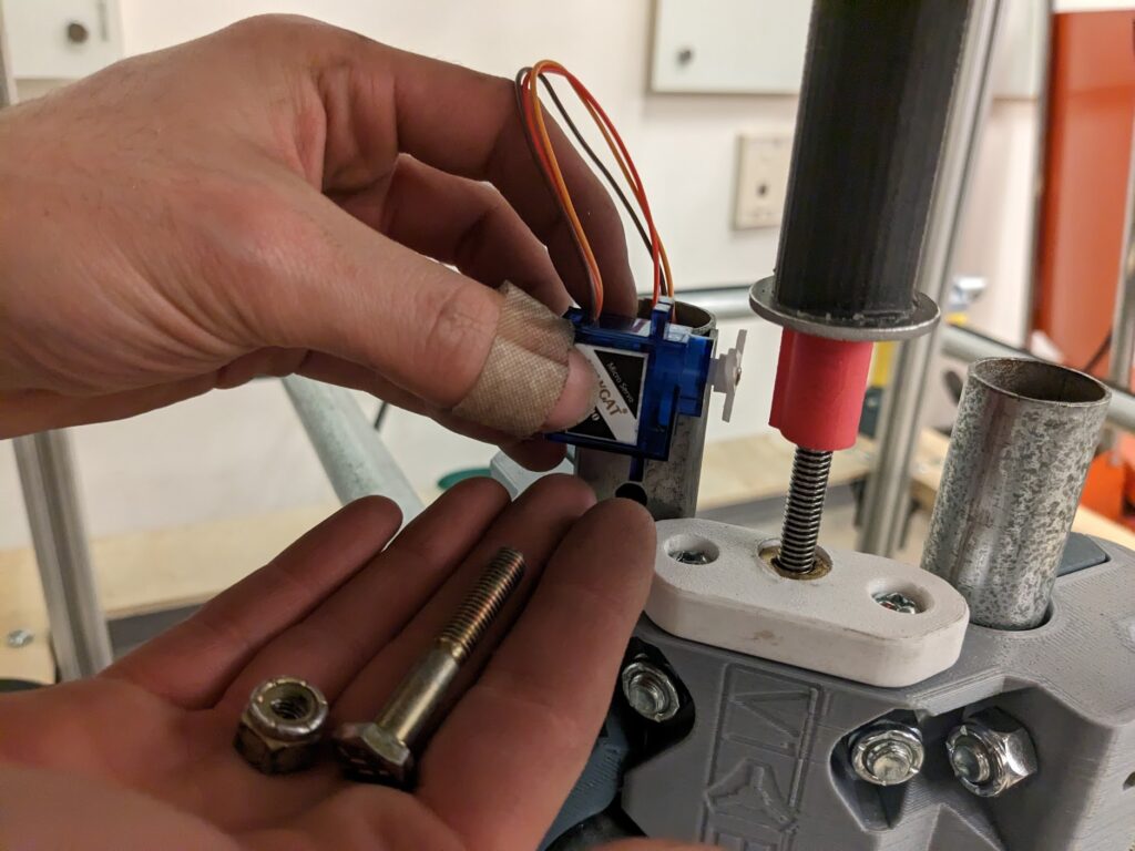
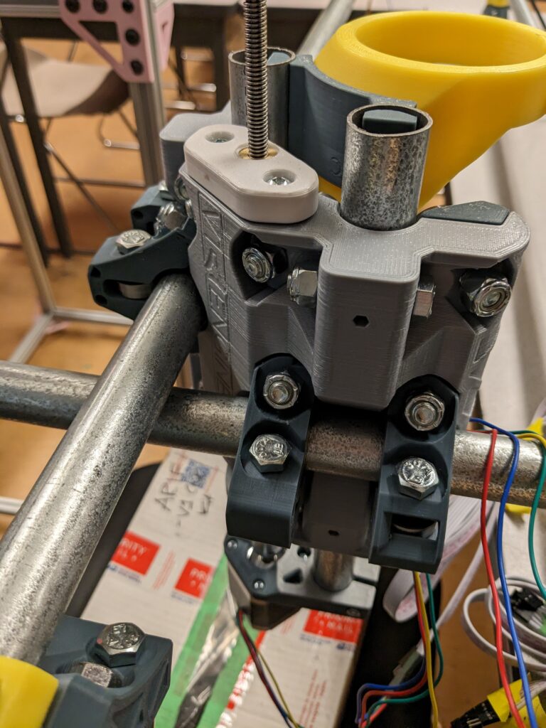
The concepts ended up being more complex than our final implementation. Our implemented solution was to use a keyed shaft and a spring on a cone-shaped vertical funnel. this funnel had a lofted hexagonal pocket from top to bottom, which started larger before settling to the size of a 1/4-20″ nut. Then we welded a nut to the bottom of every pin:
This system allows for about 4cm of acceptable inaccuracy in the z translation of the pin actuator as it rotates a pin. The spring means that as the actuator raises, the funnel will be pressed down slightly until it “pops” into engagement with each nut. When the pin has reached its final position, the servo motor pulls down the funnel so that the z actuator can lower.
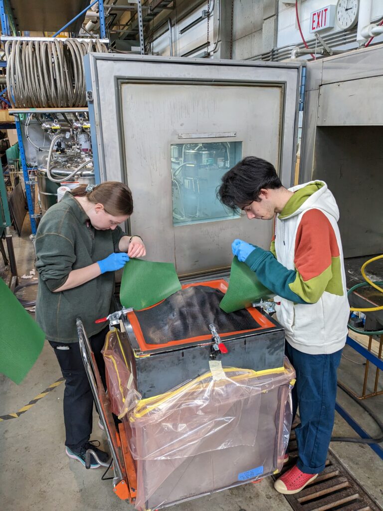
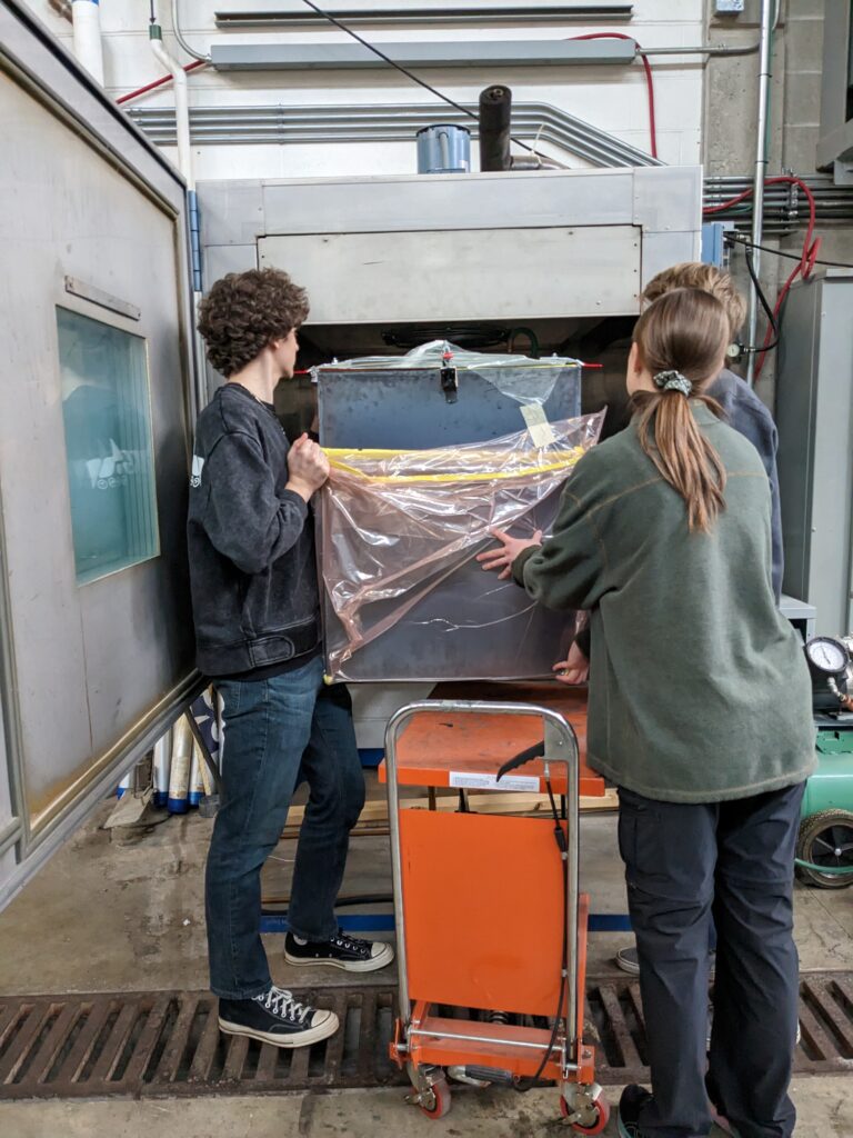
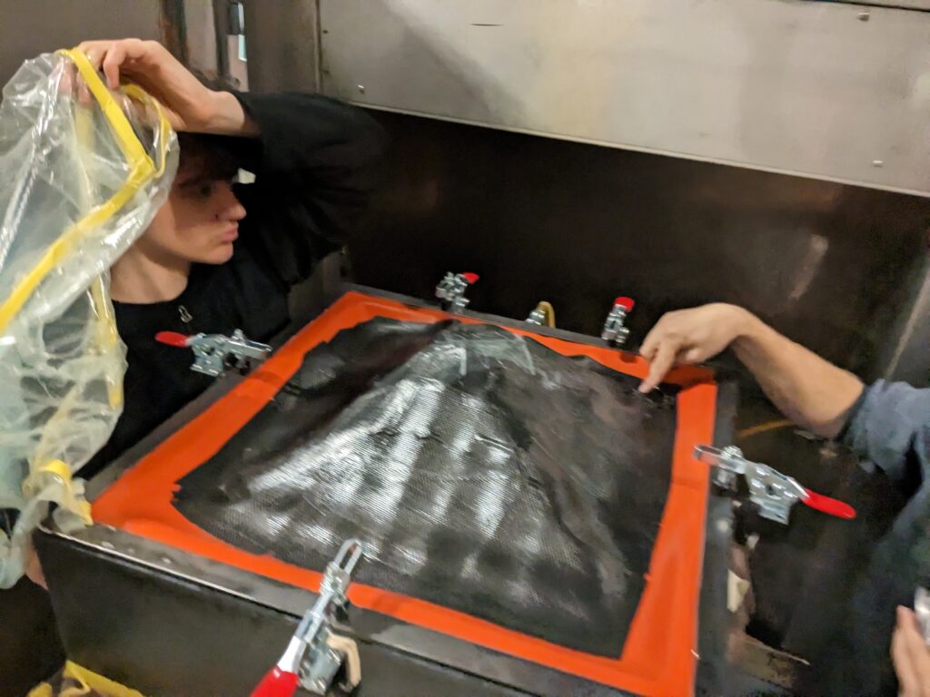
The rest of the design was centered around a three-part system. The pin array (mold), the configurator, and the vacuum box. The pin array is placed onto the configurator, which holds the CNC gantry and all electronics. The configurator sets each pin into the right position, and then the user pulls the pin array off and places it into the vacuum box. They then clamp the silicone layer over the pin array and hook up a vacuum pump to the box. This design allows us to keep all the heat-sensitive electronics out of the oven, and also allows the silicone layer to be easily swapped out after significant use, or for custom top surfaces to be used for different applications.
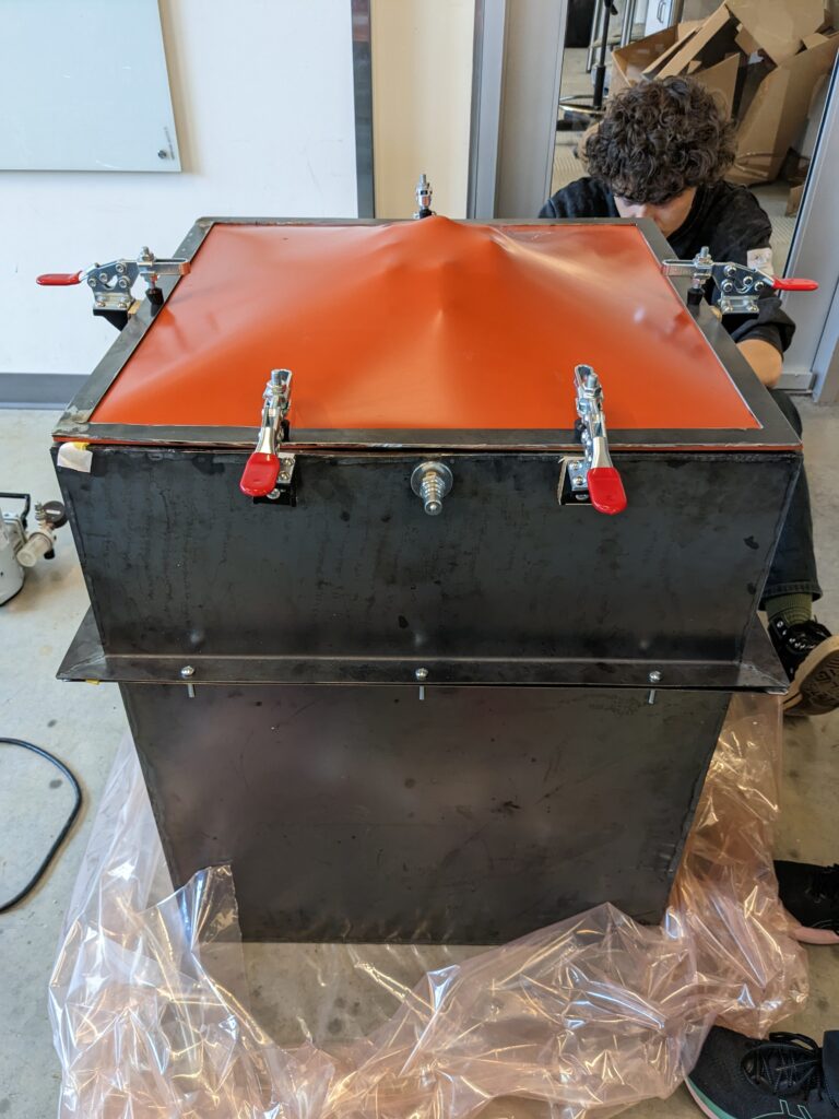
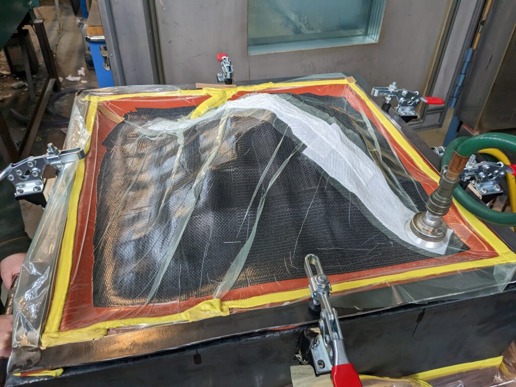
Finally, the composite material is laid up on the surface and a vacuum bag layer is created around the top. Both vacuum lines are fed out of the curing oven:
We presented our prototype design to the UBC community at UBC’s annual Design and Innovation Day and ended up winning the Top Design Award in the third year project category! Our team put so much work into this design and we were really proud of what we were able to accomplish, even though its results are fairly rudimentary. I’m interested in taking this project further with my team in the future, and developing systems to solve some of the key problems with our design: surface waffling, low-resolution, and especially the design’s limitation of being unable to produce sharp edges of any kind. The team and I have several ideas for all these issues, and I look forward to sharing more about this project in years to come!
Please find our final presentation poster and final project report below!
Leave a Reply